sh030106u.pdf - 第497页
14. USIN G A LINEAR SER VO MOTOR 14 - 30 14.4 Charac teristic s 14.4.1 Ov erload pr otecti on char acteristic s An electr onic th erma l is bui lt in the servo ampli fier to pr otec t th e lin ear serv o motor , serv o a…
14. USING A LINEAR SERVO MOTOR
14 - 29
(2) Auto tuning function
POINT
The auto tuning mode 1 may not be performed properly if the following
conditions are not satisfied.
Time to reach 2000 mm/s is the acceleration/deceleration time constant of 5 s
or less.
The linear servo motor speed is 150 mm/s or higher.
The load to mass of the linear servo motor primary-side ratio is 100 times or
less.
The acceleration/deceleration thrust is 10% or less of the continuous thrust.
The auto tuning function during the linear servo motor operation is the same as that of the rotary servo
motor. However, the calculation method of the load to motor mass ratio (J ratio) differs. The load to
motor mass ratio (J ratio) on the linear servo motor is calculated by dividing the load mass by the mass
of the linear servo motor primary side.
Example) Mass of linear servo motor primary side
Load mass (excluding the mass of the linear servo motor primary side)
Mass ratio
= 2 kg
= 4 kg
= 4/2 = 2 times
For the parameters set by the auto tuning function, refer to chapter 6.
(3) Machine analyzer function
POINT
Make sure to perform the machine analyzer function after the magnetic pole
detection. If the magnetic pole detection is not performed, the machine analyze
function may not operate properly.
The stop position at the completion of the machine analyzer function can be any
position.
14.3.7 Absolute position detection system
When the linear servo motor is used with the absolute position detection system, an absolute position linear
encoder is required. The linear encoder backs up the absolute position data. Therefore, the encoder battery
need not be installed to the servo amplifier. Additionally, [AL. 25 Absolute position erased], [AL. 92 Battery
cable disconnection warning], [AL. 9F Battery warning], and [AL. E3 Absolute position counter warning] are
not provided for the linear servo motor.
14. USING A LINEAR SERVO MOTOR
14 - 30
14.4 Characteristics
14.4.1 Overload protection characteristics
An electronic thermal is built in the servo amplifier to protect the linear servo motor, servo amplifier and linear
servo motor power wires from overloads.
[AL. 50 Overload 1] occurs if overload operation performed is above the electronic thermal protection curve
shown in fig. 14.2. [AL. 51 Overload 2] occurs if the maximum current is applied continuously for several
seconds due to machine collision, etc. Use the equipment on the left-side area of the continuous or broken
line in the graph.
Use the linear servo motor with 70% or less of the effective load ratio when it is in the servo lock state or in a
small reciprocating motion.
This servo amplifier has solid-state linear servo motor overload protection. (The servo motor overload current
(full load current) is set on the basis of 120% rated current of the servo amplifier.)
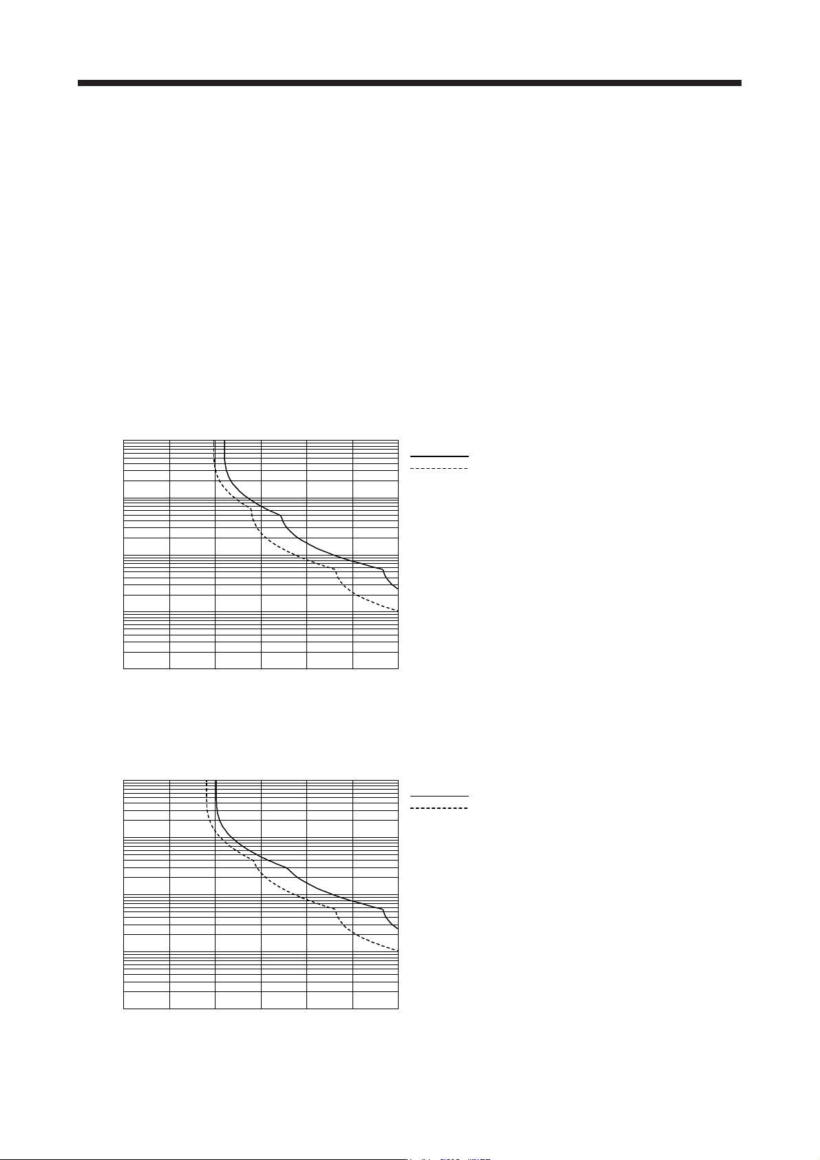
(1) LM-H3 series
50 100 150 200 250 3000
0.1
10
1
100
1000
[%]
Operation time [s]
Load ratio
: Operating
: Servo-lock
(2) LM-K2 series
15010050 200 250 3000
0.1
10
1
100
1000
[%]
Operation time [s]
Load ratio
: Operating
: Servo-lock
14. USING A LINEAR SERVO MOTOR
14 - 31
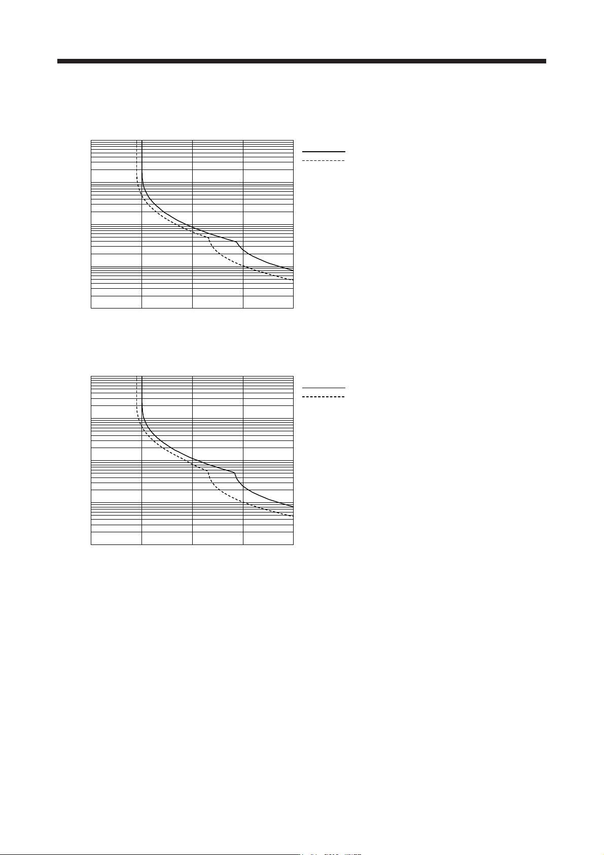
(3) LM-U2 series
(a) LM-U2PBD-15M-1SS0
400100 200 3000
0.1
10
1
100
1000
[%]
Operation time [s]
Load ratio
: Operating
: Servo-lock
(b) Other than LM-U2PBD-15M-1SS0
0
0.1
10
1
100
1000
[%]
100 200 300 400
Load ratio
: Operating
: Servo-lock
Operation time [s]