sh030106u.pdf - 第500页
14. USING A LINE AR SERVO MOTO R 14 - 33 (b) Other tha n LM- FP2B- 06M-1S S0 (liqu id cool ing) 50 100 150 200 250 300 0 0.1 10 1 100 1000 [%] Load ratio : Operating : Servo-lock Operation time [s]
14. USING A LINEAR SERVO MOTOR
14 - 32
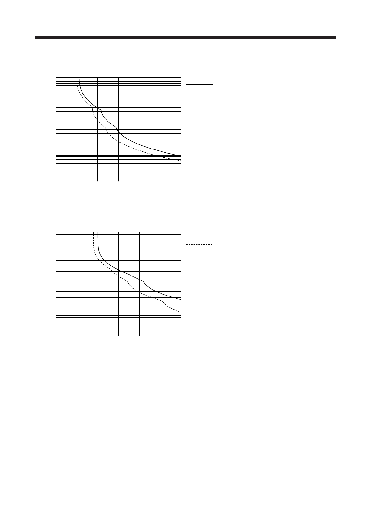
(4) LM-F series (natural cooling)
100 200 300 400 500 6000
0.1
10
1
100
1000
[%]
Load ratio
: Operating
: Servo-lock
Operation time [s]
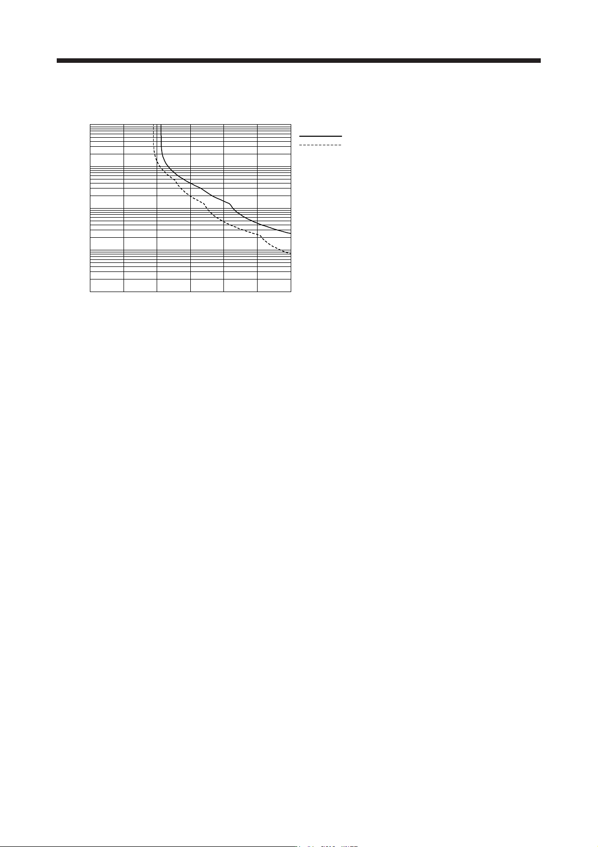
(5) LM-F series (liquid cooling)
(a) LM-FP2B-06M-1SS0 (liquid cooling)
300150 20050 100 2500
0.1
10
1
100
1000
[%]
Operation time [s]
Load ratio
: Operating
: Servo-lock
14. USING A LINEAR SERVO MOTOR
14 - 33
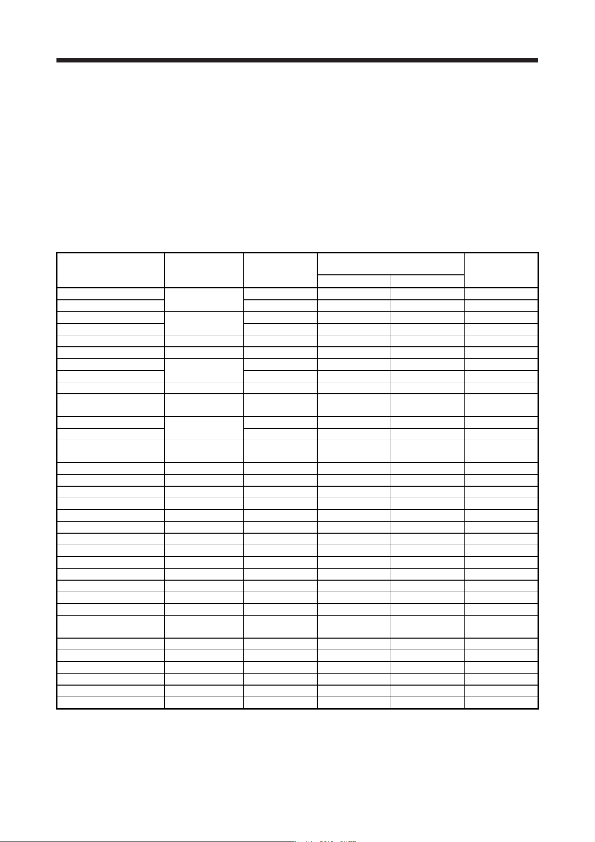
(b) Other than LM-FP2B-06M-1SS0 (liquid cooling)
50 100 150 200 250 3000
0.1
10
1
100
1000
[%]Load ratio
: Operating
: Servo-lock
Operation time [s]
14. USING A LINEAR SERVO MOTOR
14 - 34
14.4.2 Power supply capacity and generated loss
Table 14.1 indicates servo amplifiers' power supply capacities and losses generated under rated load. For
thermal design of an enclosed type cabinet, use the values in the tables in consideration for the harshest
conditions with regard to the environment and operation pattern. The actual amount of generated heat will be
intermediate between values at rated torque and servo-off according to the duty used during operation.
When the linear servo motor is run at less than the rated speed, the power supply capacity will be smaller
than the value in the table, but the servo amplifier's generated heat will not change.
Mounting a heat sink outside of the cabinet enables to reduce heat in the cabinet and design a compact
enclosed type cabinet.
Table 14.1 Power supply capacity and generated loss per linear servo motor
Linear servo motor
(primary side)
Servo amplifier
Power supply
capacity [kVA]
(Note 1)
Servo amplifier-generated heat [W]
(Note 2)
Area required for
heat dissipation
[m
2
]
At rated output With servo-off
LM-H3P2A-07P-BSS0
MR-J4-40B(-RJ)
MR-J4-40B1(-RJ)
0.9 35 15 0.7
LM-H3P3A-12P-CSS0 0.9 35 15 0.7
LM-H3P3B-24P-CSS0
MR-J4-70B(-RJ)
1.3 50 15 1.0
LM-H3P3C-36P-CSS0 1.9 75 15 1.5
LM-H3P3D-48P-CSS0 MR-J4-200B(-RJ) 3.5 90 20 1.8
LM-H3P7A-24P-ASS0 MR-J4-70B(-RJ) 1.3 50 15 1.0
LM-H3P7B-48P-ASS0
MR-J4-200B(-RJ)
3.5 90 20 1.8
LM-H3P7C-72P-ASS0 3.8 100 20 1.1
LM-H3P7D-96P-ASS0 MR-J4-350B(-RJ) 5.5 130 20 2.7
LM-U2PAB-05M-0SS0
MR-J4-20B(-RJ)
MR-J4-20B1(-RJ)
0.5 25 15 0.5
LM-U2PAD-10M-0SS0
MR-J4-40B(-RJ)
MR-J4-40B1(-RJ)
0.9 35 15 0.7
LM-U2PAF-15M-0SS0 0.9 35 15 0.7
LM-U2PBB-07M-1SS0
MR-J4-20B(-RJ)
MR-J4-20B1(-RJ)
0.5 25 15 0.5
LM-U2PBD-15M-1SS0 MR-J4-60B(-RJ) 1.0 40 15 0.8
LM-U2PBF-22M-1SS0 MR-J4-70B(-RJ) 1.3 50 15 1.0
LM-U2P2B-40M-2SS0 MR-J4-200B(-RJ) 3.5 90 20 1.8
LM-U2P2C-60M-2SS0 MR-J4-350B(-RJ) 5.5 130 20 2.7
LM-U2P2D-80M-2SS0 MR-J4-500B(-RJ) 7.5 195 25 3.9
LM-FP2B-06M-1SS0 MR-J4-200B(-RJ) 3.5 90 20 1.8
LM-FP2D-12M-1SS0 MR-J4-500B(-RJ) 7.5 195 25 3.9
LM-FP2F-18M-1SS0 MR-J4-700B(-RJ) 10 300 25 6.0
LM-FP4B-12M-1SS0 MR-J4-500B(-RJ) 7.5 195 25 3.9
LM-FP4D-24M-1SS0 MR-J4-700B(-RJ) 10 300 25 6.0
LM-FP4F-36M-1SS0 MR-J4-11KB(-RJ) 14 460 45 9.2
LM-FP4H-48M-1SS0 MR-J4-15KB(-RJ) 18 580 45 11.6
LM-FP5H-60M-1SS0 MR-J4-22KB4(-RJ) 22 640 45 12.8
LM-K2P1A-01M-2SS1
MR-J4-40B(-RJ)
MR-J4-40B1(-RJ)
0.9 35 15 0.7
LM-K2P1C-03M-2SS1 MR-J4-200B(-RJ) 3.5 90 20 1.8
LM-K2P2A-02M-1SS1 MR-J4-70B(-RJ) 1.3 50 15 1.0
LM-K2P2C-07M-1SS1 MR-J4-350B(-RJ) 5.5 130 20 2.7
LM-K2P2E-12M-1SS1 MR-J4-500B(-RJ) 7.5 195 25 3.9
LM-K2P3C-14M-1SS1 MR-J4-350B(-RJ) 5.5 130 20 2.7
LM-K2P3E-24M-1SS1 MR-J4-500B(-RJ) 7.5 195 25 3.9
Note 1. The power supply equipment capacity changes with the power supply impedance. This value is applicable when the power
factor improvin
g
AC reactor or power factor improvin
g
DC reactor is not used.
2. Heat generated during regeneration is not included in the servo amplifier-generated heat. To calculate heat generated by the
re
g
enerative option, refer to section 11.2.