sh030106u.pdf - 第502页
14. USIN G A LINEAR SER VO MOTOR 14 - 35 14.4.3 Dyna mic br ake char acter istics CAUTION The coasti ng dis tance is a t heoretic ally c alculate d val ue that does not consid er factors suc h as fricti on. The calcul at…
14. USING A LINEAR SERVO MOTOR
14 - 34
14.4.2 Power supply capacity and generated loss
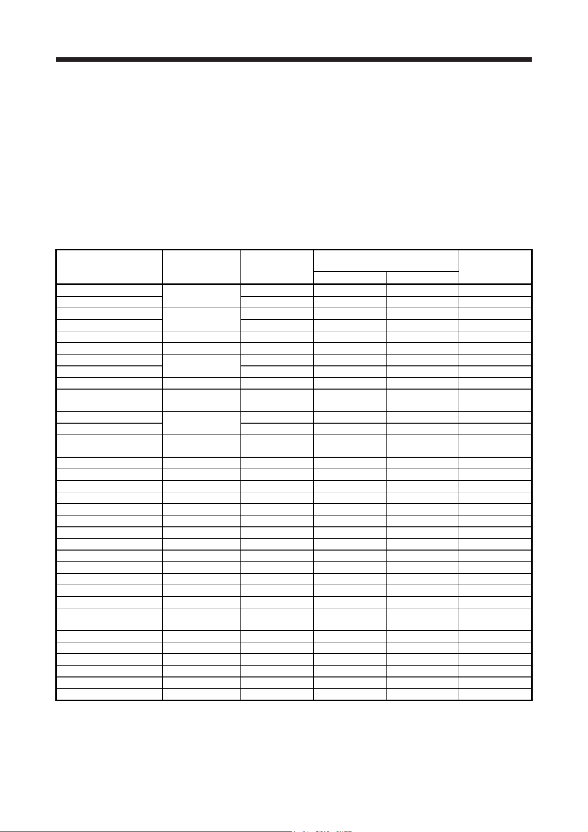
Table 14.1 indicates servo amplifiers' power supply capacities and losses generated under rated load. For
thermal design of an enclosed type cabinet, use the values in the tables in consideration for the harshest
conditions with regard to the environment and operation pattern. The actual amount of generated heat will be
intermediate between values at rated torque and servo-off according to the duty used during operation.
When the linear servo motor is run at less than the rated speed, the power supply capacity will be smaller
than the value in the table, but the servo amplifier's generated heat will not change.
Mounting a heat sink outside of the cabinet enables to reduce heat in the cabinet and design a compact
enclosed type cabinet.
Table 14.1 Power supply capacity and generated loss per linear servo motor
Linear servo motor
(primary side)
Servo amplifier
Power supply
capacity [kVA]
(Note 1)
Servo amplifier-generated heat [W]
(Note 2)
Area required for
heat dissipation
[m
2
]
At rated output With servo-off
LM-H3P2A-07P-BSS0
MR-J4-40B(-RJ)
MR-J4-40B1(-RJ)
0.9 35 15 0.7
LM-H3P3A-12P-CSS0 0.9 35 15 0.7
LM-H3P3B-24P-CSS0
MR-J4-70B(-RJ)
1.3 50 15 1.0
LM-H3P3C-36P-CSS0 1.9 75 15 1.5
LM-H3P3D-48P-CSS0 MR-J4-200B(-RJ) 3.5 90 20 1.8
LM-H3P7A-24P-ASS0 MR-J4-70B(-RJ) 1.3 50 15 1.0
LM-H3P7B-48P-ASS0
MR-J4-200B(-RJ)
3.5 90 20 1.8
LM-H3P7C-72P-ASS0 3.8 100 20 1.1
LM-H3P7D-96P-ASS0 MR-J4-350B(-RJ) 5.5 130 20 2.7
LM-U2PAB-05M-0SS0
MR-J4-20B(-RJ)
MR-J4-20B1(-RJ)
0.5 25 15 0.5
LM-U2PAD-10M-0SS0
MR-J4-40B(-RJ)
MR-J4-40B1(-RJ)
0.9 35 15 0.7
LM-U2PAF-15M-0SS0 0.9 35 15 0.7
LM-U2PBB-07M-1SS0
MR-J4-20B(-RJ)
MR-J4-20B1(-RJ)
0.5 25 15 0.5
LM-U2PBD-15M-1SS0 MR-J4-60B(-RJ) 1.0 40 15 0.8
LM-U2PBF-22M-1SS0 MR-J4-70B(-RJ) 1.3 50 15 1.0
LM-U2P2B-40M-2SS0 MR-J4-200B(-RJ) 3.5 90 20 1.8
LM-U2P2C-60M-2SS0 MR-J4-350B(-RJ) 5.5 130 20 2.7
LM-U2P2D-80M-2SS0 MR-J4-500B(-RJ) 7.5 195 25 3.9
LM-FP2B-06M-1SS0 MR-J4-200B(-RJ) 3.5 90 20 1.8
LM-FP2D-12M-1SS0 MR-J4-500B(-RJ) 7.5 195 25 3.9
LM-FP2F-18M-1SS0 MR-J4-700B(-RJ) 10 300 25 6.0
LM-FP4B-12M-1SS0 MR-J4-500B(-RJ) 7.5 195 25 3.9
LM-FP4D-24M-1SS0 MR-J4-700B(-RJ) 10 300 25 6.0
LM-FP4F-36M-1SS0 MR-J4-11KB(-RJ) 14 460 45 9.2
LM-FP4H-48M-1SS0 MR-J4-15KB(-RJ) 18 580 45 11.6
LM-FP5H-60M-1SS0 MR-J4-22KB4(-RJ) 22 640 45 12.8
LM-K2P1A-01M-2SS1
MR-J4-40B(-RJ)
MR-J4-40B1(-RJ)
0.9 35 15 0.7
LM-K2P1C-03M-2SS1 MR-J4-200B(-RJ) 3.5 90 20 1.8
LM-K2P2A-02M-1SS1 MR-J4-70B(-RJ) 1.3 50 15 1.0
LM-K2P2C-07M-1SS1 MR-J4-350B(-RJ) 5.5 130 20 2.7
LM-K2P2E-12M-1SS1 MR-J4-500B(-RJ) 7.5 195 25 3.9
LM-K2P3C-14M-1SS1 MR-J4-350B(-RJ) 5.5 130 20 2.7
LM-K2P3E-24M-1SS1 MR-J4-500B(-RJ) 7.5 195 25 3.9
Note 1. The power supply equipment capacity changes with the power supply impedance. This value is applicable when the power
factor improvin
g
AC reactor or power factor improvin
g
DC reactor is not used.
2. Heat generated during regeneration is not included in the servo amplifier-generated heat. To calculate heat generated by the
re
g
enerative option, refer to section 11.2.
14. USING A LINEAR SERVO MOTOR
14 - 35
14.4.3 Dynamic brake characteristics
CAUTION
The coasting distance is a theoretically calculated value that does not consider
factors such as friction. The calculated distance is longer than the actual distance.
If the braking distance is not longer than the calculated value, a moving part may
crash into the stroke end, causing a dangerous situation. Install an anti-crash
mechanism such as an air brake or an electric/mechanical stopper such as a
shock absorber to reduce the shock of moving parts.
POINT
Do not use dynamic brake to stop in a normal operation as it is the function to
stop in emergency.
For a machine operating at the recommended load to motor mass ratio or less,
the estimated number of usage times of the dynamic brake is 1000 times while
the machine decelerates from the rated speed to a stop once in 10 minutes.
Be sure to enable EM1 (Forced stop 1) after the linear servo motor stops when
using EM1 (Forced stop 1) frequently in other than emergency.
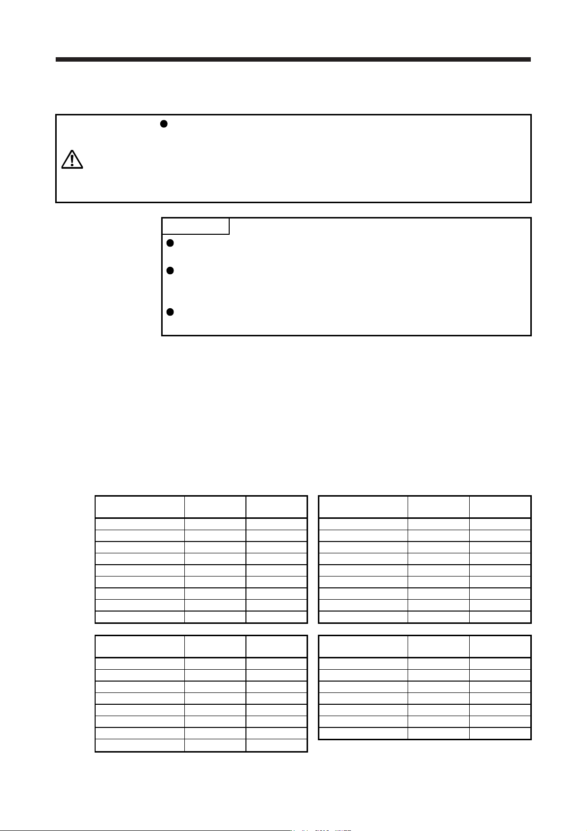
The approximate coasting distance from when the dynamic brake is activated until when the linear servo
motor stops can be calculated with the equation below.
Lmax = V
0
• (0.03 + M • (A + B • V
0
2
))
Lmax: Coasting distance of the machine [m]
V
0
: Speed when the brake is activated [m/s]
M: Full mass of the moving part [kg]
A: Coefficient (Refer to the following tables.)
B: Coefficient (Refer to the following tables.)
Linear servo motor
(primary side)
Coefficient A Coefficient B
Linear servo motor
(primary side)
Coefficient A Coefficient B
LM-H3P2A-07P-BSS0 7.15 × 10
-3
2.94 × 10
-3
LM-U2PAB-05M-0SS0 5.72 × 10
-2
1.72 × 10
-4
LM-H3P3A-12P-CSS0 2.81 × 10
-3
1.47 × 10
-3
LM-U2PAD-10M-0SS0 2.82 × 10
-2
8.60 × 10
-5
LM-H3P3B-24P-CSS0 7.69 × 10
-3
2.27 × 10
-4
LM-U2PAF-15M-0SS0 1.87 × 10
-2
5.93 × 10
-5
LM-H3P3C-36P-CSS0 7.22 × 10
-3
1.13 × 10
-4
LM-U2PBB-07M-1SS0 3.13 × 10
-2
1.04 × 10
-4
LM-H3P3D-48P-CSS0 1.02 × 10
-3
2.54 × 10
-4
LM-U2PBD-15M-1SS0 1.56 × 10
-2
5.18 × 10
-5
LM-H3P7A-24P-ASS0 7.69 × 10
-3
2.14 × 10
-4
LM-U2PBF-22M-1SS0 4.58 × 10
-2
1.33 × 10
-5
LM-H3P7B-48P-ASS0 9.14 × 10
-4
2.59 × 10
-4
LM-U2P2B-40M-2SS0 1.47 × 10
-3
1.27 × 10
-5
LM-H3P7C-72P-ASS0 7.19 × 10
-4
1.47 × 10
-4
LM-U2P2C-60M-2SS0 1.07 × 10
-3
7.66 × 10
-6
LM-H3P7D-96P-ASS0 6.18 × 10
-4
9.59 × 10
-5
LM-U2P2D-80M-2SS0 9.14 × 10
-4
5.38 × 10
-6
Linear servo motor
(primary side)
Coefficient A Coefficient B
Linear servo motor
(primary side)
Coefficient A Coefficient B
LM-FP2B-06M-1SS0 8.96 × 10
-4
1.19 × 10
-3
LM-K2P1A-01M-2SS1 5.36 × 10
-3
6.56 × 10
-3
LM-FP2D-12M-1SS0 5.55 × 10
-4
4.81 × 10
-4
LM-K2P1C-03M-2SS1 1.17 × 10
-3
3.75 × 10
-4
LM-FP2F-18M-1SS0 4.41 × 10
-4
2.69 × 10
-4
LM-K2P2A-02M-1SS1 2.49 × 10
-2
1.02 × 10
-3
LM-FP4B-12M-1SS0 5.02 × 10
-4
4.36 × 10
-4
LM-K2P2C-07M-1SS1 6.85 × 10
-4
2.80 × 10
-4
LM-FP4D-24M-1SS0 3.55 × 10
-4
1.54 × 10
-4
LM-K2P2E-12M-1SS1 5.53 × 10
-4
1.14 × 10
-4
LM-FP4F-36M-1SS0 1.79 × 10
-4
1.36 × 10
-4
LM-K2P3C-14M-1SS1 2.92 × 10
-4
1.16 × 10
-4
LM-FP4H-48M-1SS0 1.15 × 10
-4
1.19 × 10
-4
LM-K2P3E-24M-1SS1 2.53 × 10
-4
5.52 × 10
-5
LM-FP5H-60M-1SS0 1.95 × 10
-4
4.00 × 10
-5
14. USING A LINEAR SERVO MOTOR
14 - 36
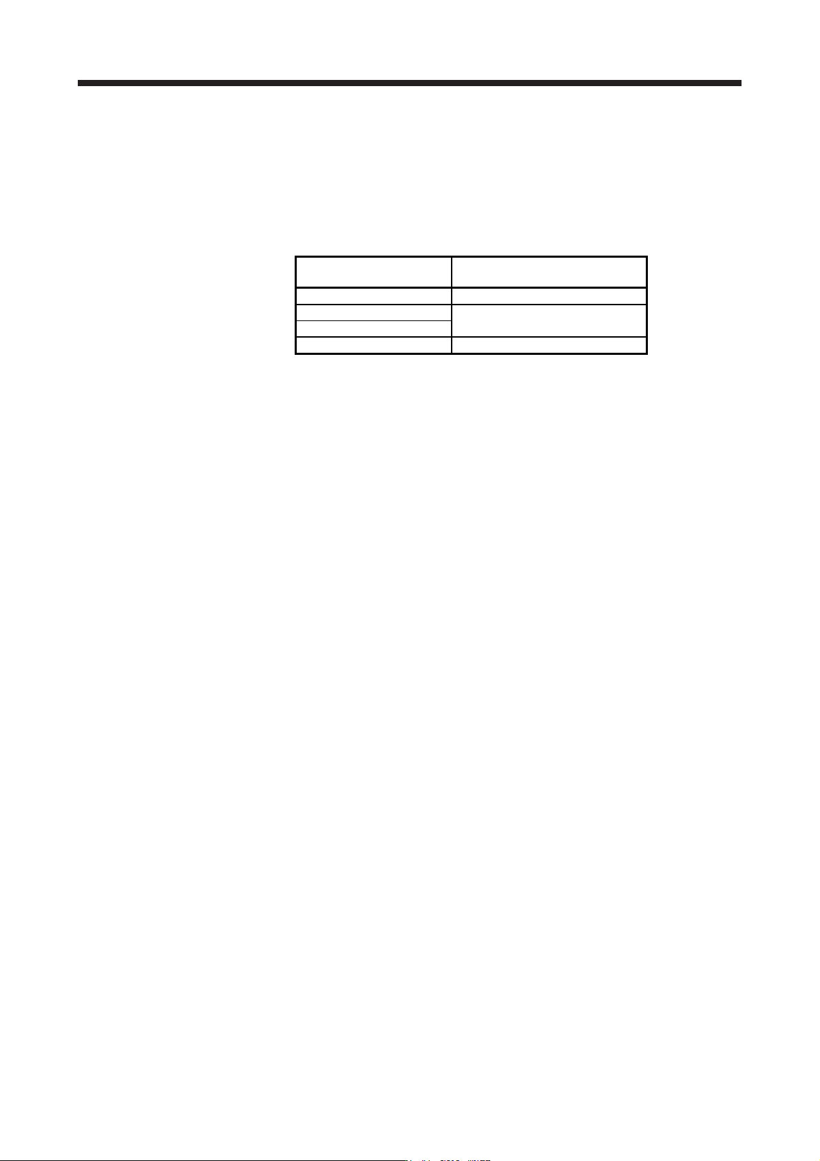
14.4.4 Permissible load to motor mass ratio when the dynamic brake is used
Use the dynamic brake under the load to motor mass ratio indicated in the following table. If the load to
motor mass ratio is higher than this value, the dynamic brake may burn. If there is a possibility that the load
inertia moment may exceed the value, contact your local sales office.
The values of the permissible load to motor mass ratio in the table are the values when the linear servo
motor is used at the maximum speed.
Linear servo motor
(primary side)
Permissible load to motor mass ratio
[multiplier]
LM-H3 series 40
LM-U2 series
100
LM-F series
LM-K2 series 50
When actual speed does not reach the maximum speed of the linear servo motor, calculate the permissible
load to motor mass ratio at the time of using the dynamic brake by the following equation. (The upper limit is
300 times.)
Permissible load to motor mass ratio at the time of using the dynamic brake = Value in the table × (Servo
motor maximum speed
2
/Actual using speed
2
)
For example, when an actual using speed is 2 m/s or less for the LM-H3P2A-07P motor (maximum speed:
3.0 m/s), the equation will be as follows. Permissible load to motor mass ratio at the time of using the
dynamic brake = 40 × 3
2
/2
2
= 90 [times]