sh030106u.pdf - 第503页
14. USIN G A LINEAR SER VO MOTOR 14 - 36 14.4.4 Per missi ble lo ad to motor mas s ratio wh en the dynam ic br ak e is us ed Use the dy namic br ake und er the load to motor m ass r atio in dica ted in the f ollow ing ta…
14. USING A LINEAR SERVO MOTOR
14 - 35
14.4.3 Dynamic brake characteristics
CAUTION
The coasting distance is a theoretically calculated value that does not consider
factors such as friction. The calculated distance is longer than the actual distance.
If the braking distance is not longer than the calculated value, a moving part may
crash into the stroke end, causing a dangerous situation. Install an anti-crash
mechanism such as an air brake or an electric/mechanical stopper such as a
shock absorber to reduce the shock of moving parts.
POINT
Do not use dynamic brake to stop in a normal operation as it is the function to
stop in emergency.
For a machine operating at the recommended load to motor mass ratio or less,
the estimated number of usage times of the dynamic brake is 1000 times while
the machine decelerates from the rated speed to a stop once in 10 minutes.
Be sure to enable EM1 (Forced stop 1) after the linear servo motor stops when
using EM1 (Forced stop 1) frequently in other than emergency.
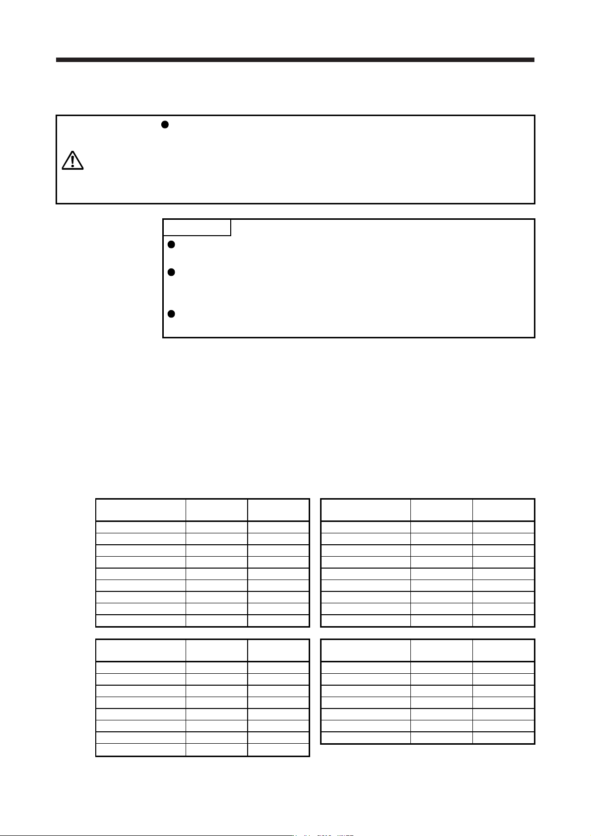
The approximate coasting distance from when the dynamic brake is activated until when the linear servo
motor stops can be calculated with the equation below.
Lmax = V
0
• (0.03 + M • (A + B • V
0
2
))
Lmax: Coasting distance of the machine [m]
V
0
: Speed when the brake is activated [m/s]
M: Full mass of the moving part [kg]
A: Coefficient (Refer to the following tables.)
B: Coefficient (Refer to the following tables.)
Linear servo motor
(primary side)
Coefficient A Coefficient B
Linear servo motor
(primary side)
Coefficient A Coefficient B
LM-H3P2A-07P-BSS0 7.15 × 10
-3
2.94 × 10
-3
LM-U2PAB-05M-0SS0 5.72 × 10
-2
1.72 × 10
-4
LM-H3P3A-12P-CSS0 2.81 × 10
-3
1.47 × 10
-3
LM-U2PAD-10M-0SS0 2.82 × 10
-2
8.60 × 10
-5
LM-H3P3B-24P-CSS0 7.69 × 10
-3
2.27 × 10
-4
LM-U2PAF-15M-0SS0 1.87 × 10
-2
5.93 × 10
-5
LM-H3P3C-36P-CSS0 7.22 × 10
-3
1.13 × 10
-4
LM-U2PBB-07M-1SS0 3.13 × 10
-2
1.04 × 10
-4
LM-H3P3D-48P-CSS0 1.02 × 10
-3
2.54 × 10
-4
LM-U2PBD-15M-1SS0 1.56 × 10
-2
5.18 × 10
-5
LM-H3P7A-24P-ASS0 7.69 × 10
-3
2.14 × 10
-4
LM-U2PBF-22M-1SS0 4.58 × 10
-2
1.33 × 10
-5
LM-H3P7B-48P-ASS0 9.14 × 10
-4
2.59 × 10
-4
LM-U2P2B-40M-2SS0 1.47 × 10
-3
1.27 × 10
-5
LM-H3P7C-72P-ASS0 7.19 × 10
-4
1.47 × 10
-4
LM-U2P2C-60M-2SS0 1.07 × 10
-3
7.66 × 10
-6
LM-H3P7D-96P-ASS0 6.18 × 10
-4
9.59 × 10
-5
LM-U2P2D-80M-2SS0 9.14 × 10
-4
5.38 × 10
-6
Linear servo motor
(primary side)
Coefficient A Coefficient B
Linear servo motor
(primary side)
Coefficient A Coefficient B
LM-FP2B-06M-1SS0 8.96 × 10
-4
1.19 × 10
-3
LM-K2P1A-01M-2SS1 5.36 × 10
-3
6.56 × 10
-3
LM-FP2D-12M-1SS0 5.55 × 10
-4
4.81 × 10
-4
LM-K2P1C-03M-2SS1 1.17 × 10
-3
3.75 × 10
-4
LM-FP2F-18M-1SS0 4.41 × 10
-4
2.69 × 10
-4
LM-K2P2A-02M-1SS1 2.49 × 10
-2
1.02 × 10
-3
LM-FP4B-12M-1SS0 5.02 × 10
-4
4.36 × 10
-4
LM-K2P2C-07M-1SS1 6.85 × 10
-4
2.80 × 10
-4
LM-FP4D-24M-1SS0 3.55 × 10
-4
1.54 × 10
-4
LM-K2P2E-12M-1SS1 5.53 × 10
-4
1.14 × 10
-4
LM-FP4F-36M-1SS0 1.79 × 10
-4
1.36 × 10
-4
LM-K2P3C-14M-1SS1 2.92 × 10
-4
1.16 × 10
-4
LM-FP4H-48M-1SS0 1.15 × 10
-4
1.19 × 10
-4
LM-K2P3E-24M-1SS1 2.53 × 10
-4
5.52 × 10
-5
LM-FP5H-60M-1SS0 1.95 × 10
-4
4.00 × 10
-5
14. USING A LINEAR SERVO MOTOR
14 - 36
14.4.4 Permissible load to motor mass ratio when the dynamic brake is used
Use the dynamic brake under the load to motor mass ratio indicated in the following table. If the load to
motor mass ratio is higher than this value, the dynamic brake may burn. If there is a possibility that the load
inertia moment may exceed the value, contact your local sales office.
The values of the permissible load to motor mass ratio in the table are the values when the linear servo
motor is used at the maximum speed.
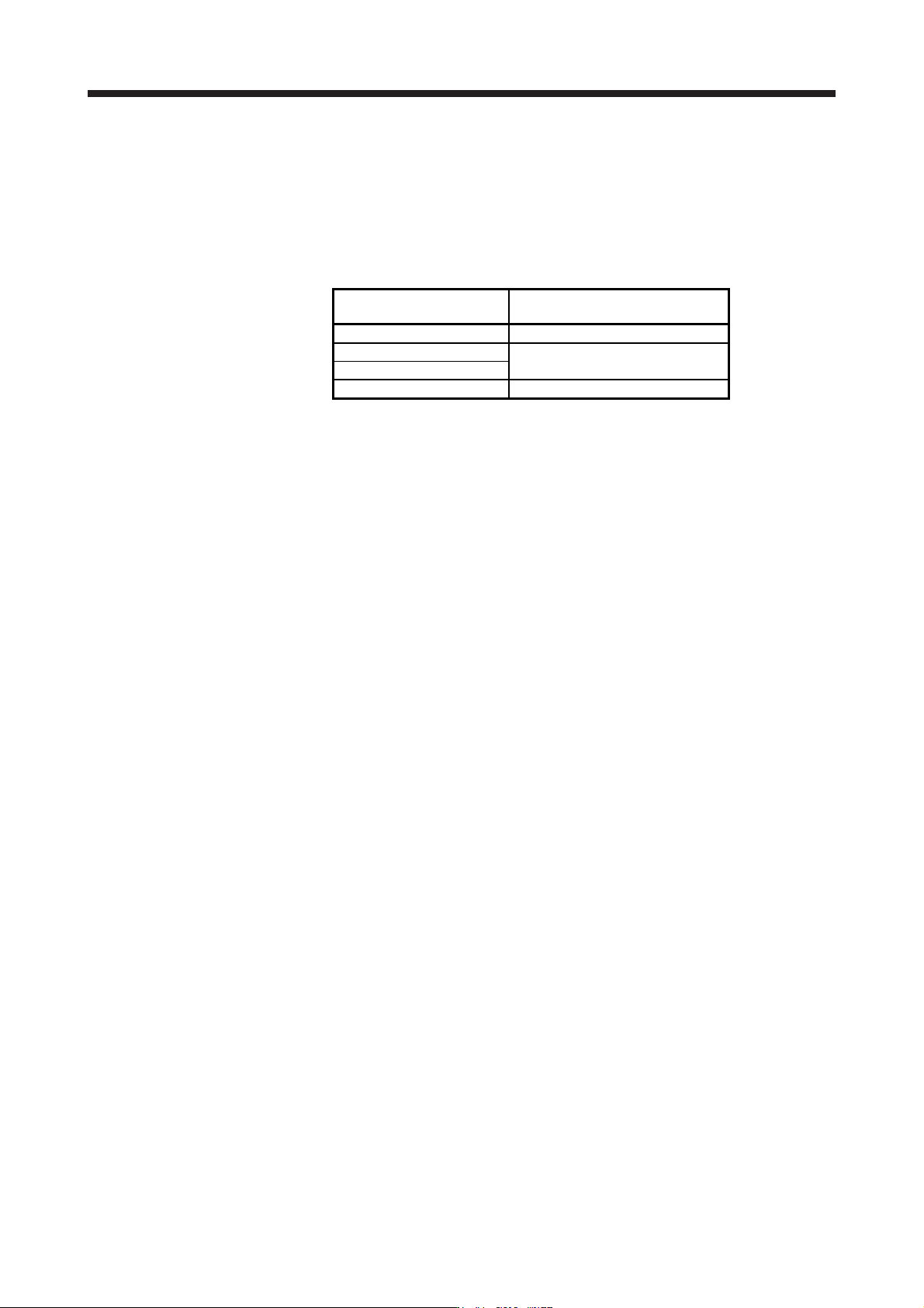
Linear servo motor
(primary side)
Permissible load to motor mass ratio
[multiplier]
LM-H3 series 40
LM-U2 series
100
LM-F series
LM-K2 series 50
When actual speed does not reach the maximum speed of the linear servo motor, calculate the permissible
load to motor mass ratio at the time of using the dynamic brake by the following equation. (The upper limit is
300 times.)
Permissible load to motor mass ratio at the time of using the dynamic brake = Value in the table × (Servo
motor maximum speed
2
/Actual using speed
2
)
For example, when an actual using speed is 2 m/s or less for the LM-H3P2A-07P motor (maximum speed:
3.0 m/s), the equation will be as follows. Permissible load to motor mass ratio at the time of using the
dynamic brake = 40 × 3
2
/2
2
= 90 [times]
15. USING A DIRECT DRIVE MOTOR
15 - 1
15. USING A DIRECT DRIVE MOTOR
CAUTION
When using the direct drive motor, read the "Direct Drive Motor Instruction
Manual".
POINT
Refer to section 1.4 for the software version of a servo amplifier that is
compatible with the direct drive servo system.
15.1 Functions and configuration
15.1.1 Summary
The fields of semiconductor/LCD manufacturing systems, mounters, and others have strong demands for
high accuracy and efficiency. Therefore, the number of systems using a direct drive motor for a drive axis
has been increasing. The direct drive servo system includes the following features.
(1) Performance
(a) The direct drive servo system ensures the high-rigidity and the high-torque. A high-resolution
encoder enables the high-accuracy control.
(b) The high-resolution encoder contributes to the high-indexer accuracy.
(c) Since reducer is no longer required, no backlash occurs. In addition, the settling time is reduced, and
the high-frequency operation is enabled.
(d) Since reducer is no longer required, the motor does not deteriorate with time by reducer.
(2) Mechanism
(a) The motor's low profile design contributes to compact moving part of the machine and a low center
of gravity for enhanced equipment stability.
(b) The motor has an inner rotor with hollow shaft which enables cables and pipes to be passed through.
(c) Lubrication and the maintenance due to abrasion are not required.
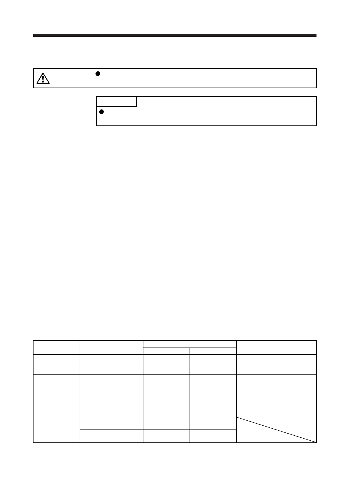
The following shows the differences between the direct drive motor and the rotary servo motor.
Category Item
Differences
Remark
Direct drive motor Rotary servo motor
External I/O signal
FLS (Upper stroke limit),
RLS (Lower stroke limit)
Required
(for magnetic pole
detection)
Not required
Automatically turns on in the
parameter setting.
Motor pole
adjustment
Magnetic pole detection Required Not required
(default setting)
Automatically executed at the first
servo-on after the power is turned
on.
For the absolute position detection
system, [Pr. PL01] can disable the
magnetic pole detection. (Refer to
(3) (a) of section 15.3.2.)
Absolute position
detection system
Absolute position encoder
battery
Required Required
Absolute position storage
unit (MR-BTAS01)
Required Not required