sh030106u.pdf - 第504页
15. USIN G A DI REC T DRIV E MOTOR 15 - 1 15. USING A DIRECT DRIVE MOTOR CAUTION When usi ng the direct dr ive motor , read the "D irect Dri ve Motor Instr uction Manual". POINT Refer to sectio n 1.4 for t he s…

14. USING A LINEAR SERVO MOTOR
14 - 36
14.4.4 Permissible load to motor mass ratio when the dynamic brake is used
Use the dynamic brake under the load to motor mass ratio indicated in the following table. If the load to
motor mass ratio is higher than this value, the dynamic brake may burn. If there is a possibility that the load
inertia moment may exceed the value, contact your local sales office.
The values of the permissible load to motor mass ratio in the table are the values when the linear servo
motor is used at the maximum speed.
Linear servo motor
(primary side)
Permissible load to motor mass ratio
[multiplier]
LM-H3 series 40
LM-U2 series
100
LM-F series
LM-K2 series 50
When actual speed does not reach the maximum speed of the linear servo motor, calculate the permissible
load to motor mass ratio at the time of using the dynamic brake by the following equation. (The upper limit is
300 times.)
Permissible load to motor mass ratio at the time of using the dynamic brake = Value in the table × (Servo
motor maximum speed
2
/Actual using speed
2
)
For example, when an actual using speed is 2 m/s or less for the LM-H3P2A-07P motor (maximum speed:
3.0 m/s), the equation will be as follows. Permissible load to motor mass ratio at the time of using the
dynamic brake = 40 × 3
2
/2
2
= 90 [times]
15. USING A DIRECT DRIVE MOTOR
15 - 1
15. USING A DIRECT DRIVE MOTOR
CAUTION
When using the direct drive motor, read the "Direct Drive Motor Instruction
Manual".
POINT
Refer to section 1.4 for the software version of a servo amplifier that is
compatible with the direct drive servo system.
15.1 Functions and configuration
15.1.1 Summary
The fields of semiconductor/LCD manufacturing systems, mounters, and others have strong demands for
high accuracy and efficiency. Therefore, the number of systems using a direct drive motor for a drive axis
has been increasing. The direct drive servo system includes the following features.
(1) Performance
(a) The direct drive servo system ensures the high-rigidity and the high-torque. A high-resolution
encoder enables the high-accuracy control.
(b) The high-resolution encoder contributes to the high-indexer accuracy.
(c) Since reducer is no longer required, no backlash occurs. In addition, the settling time is reduced, and
the high-frequency operation is enabled.
(d) Since reducer is no longer required, the motor does not deteriorate with time by reducer.
(2) Mechanism
(a) The motor's low profile design contributes to compact moving part of the machine and a low center
of gravity for enhanced equipment stability.
(b) The motor has an inner rotor with hollow shaft which enables cables and pipes to be passed through.
(c) Lubrication and the maintenance due to abrasion are not required.
The following shows the differences between the direct drive motor and the rotary servo motor.
Category Item
Differences
Remark
Direct drive motor Rotary servo motor
External I/O signal
FLS (Upper stroke limit),
RLS (Lower stroke limit)
Required
(for magnetic pole
detection)
Not required
Automatically turns on in the
parameter setting.
Motor pole
adjustment
Magnetic pole detection Required Not required
(default setting)
Automatically executed at the first
servo-on after the power is turned
on.
For the absolute position detection
system, [Pr. PL01] can disable the
magnetic pole detection. (Refer to
(3) (a) of section 15.3.2.)
Absolute position
detection system
Absolute position encoder
battery
Required Required
Absolute position storage
unit (MR-BTAS01)
Required Not required
15. USING A DIRECT DRIVE MOTOR
15 - 2
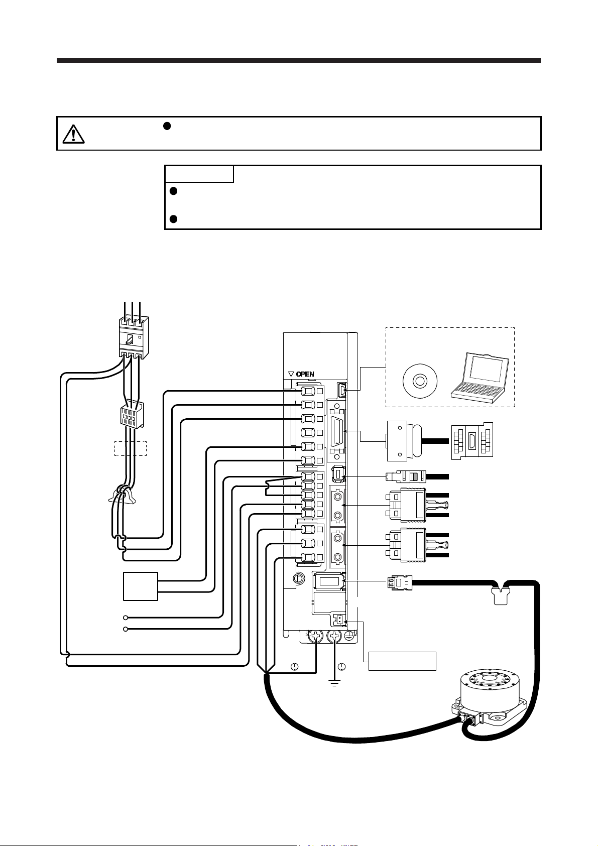
15.1.2 Servo system with auxiliary equipment
CAUTION
Connecting a direct drive motor for different axis to the U, V, W, or CN2 may
cause a malfunction.
POINT
Equipment other than the servo amplifier and direct drive motor are optional or
recommended products.
When using the direct drive motor, set [Pr. PA01] to "_ _ 6 _".
The configuration diagram is an example of MR-J4-20B. When using the other servo amplifiers, the
configuration will be the same as rotary servo motors except for connections of direct drive motors. Refer to
section 1.8 depending on servo amplifiers you use.
(Note 4)
Battery unit
CN4
(Note 6)
Absolute position
storage unit
MR-BTAS01
Direct drive motor
Line noise
filter
(FR-BSF01)
CN5
Regenerative
option
P+
C
L11
L21
P3
P4
Personal
computer
MR Configurator2
CN3
CN8
CN1A
CN1B
CN2
W
V
U
L1
L2
L3
(Note 1)
Power factor
improving DC
reactor
(FR-HEL)
Junction
terminal
block
To safety relay or
MR-J3-D05 safety
logic unit
Servo system controller
or previous servo
amplifier CN1B
Next servo amplifier
CN1A or cap
(Note 2)
Power supply
RS T
D
(Note 5)
Molded-case
circuit breaker
(MCCB)
(Note 3)
Magnetic
contactor
(MC)
(Note 7)