sh030106u.pdf - 第506页
15. USIN G A DI REC T DRIV E MOTOR 15 - 3 Note 1. The power factor improving AC react or can also be used . In this case, the power factor improv ing DC reactor c annot be used . When not usin g the power f actor improvi…
15. USING A DIRECT DRIVE MOTOR
15 - 2
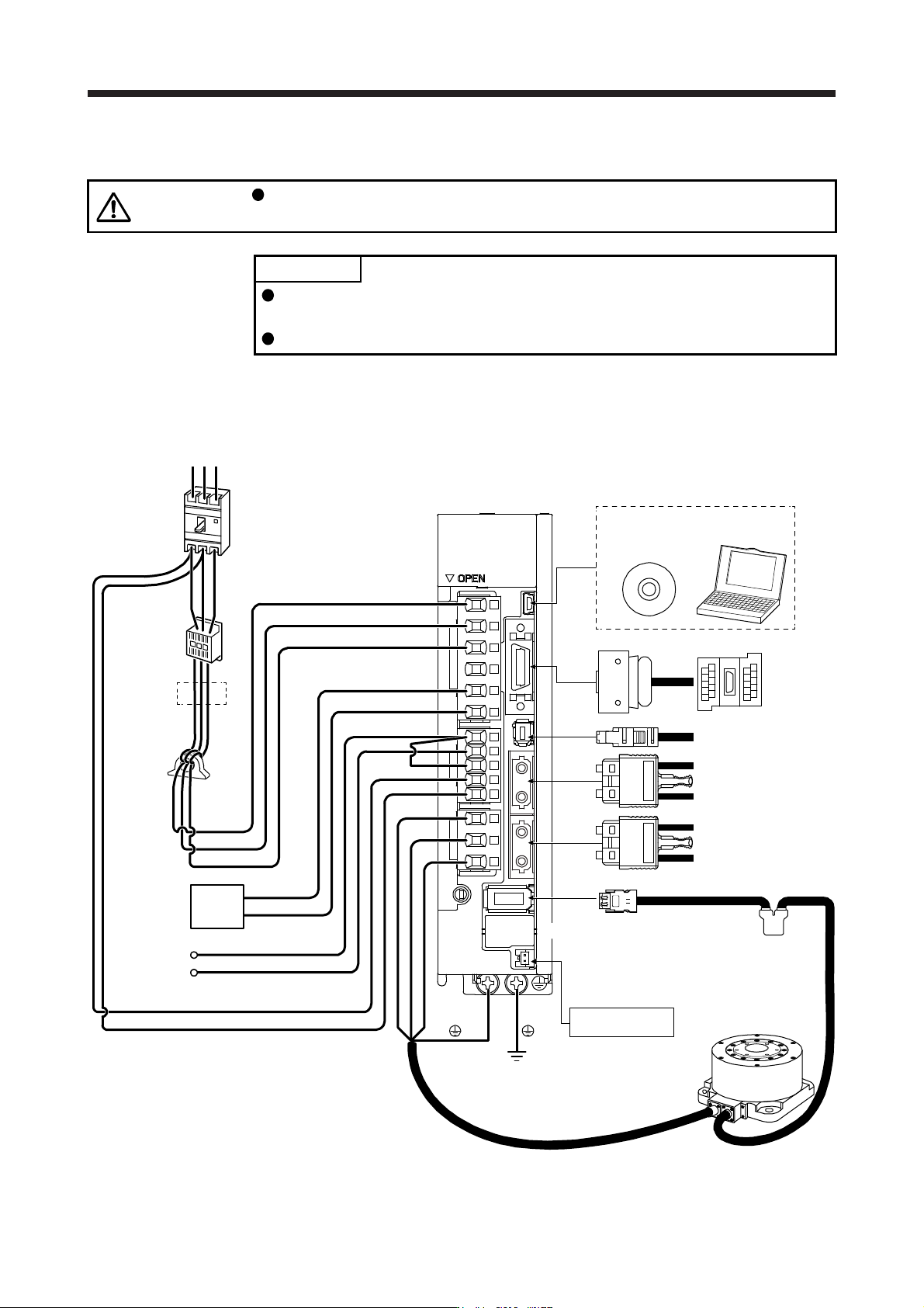
15.1.2 Servo system with auxiliary equipment
CAUTION
Connecting a direct drive motor for different axis to the U, V, W, or CN2 may
cause a malfunction.
POINT
Equipment other than the servo amplifier and direct drive motor are optional or
recommended products.
When using the direct drive motor, set [Pr. PA01] to "_ _ 6 _".
The configuration diagram is an example of MR-J4-20B. When using the other servo amplifiers, the
configuration will be the same as rotary servo motors except for connections of direct drive motors. Refer to
section 1.8 depending on servo amplifiers you use.
(Note 4)
Battery unit
CN4
(Note 6)
Absolute position
storage unit
MR-BTAS01
Direct drive motor
Line noise
filter
(FR-BSF01)
CN5
Regenerative
option
P+
C
L11
L21
P3
P4
Personal
computer
MR Configurator2
CN3
CN8
CN1A
CN1B
CN2
W
V
U
L1
L2
L3
(Note 1)
Power factor
improving DC
reactor
(FR-HEL)
Junction
terminal
block
To safety relay or
MR-J3-D05 safety
logic unit
Servo system controller
or previous servo
amplifier CN1B
Next servo amplifier
CN1A or cap
(Note 2)
Power supply
RS T
D
(Note 5)
Molded-case
circuit breaker
(MCCB)
(Note 3)
Magnetic
contactor
(MC)
(Note 7)
15. USING A DIRECT DRIVE MOTOR
15 - 3
Note 1. The power factor improving AC reactor can also be used. In this case, the power factor improving DC reactor cannot be used.
When not usin
g
the power factor improvin
g
DC reactor, short P3 and P4.
2.
A
1-phase 200 V AC to 240 V AC power supply may be used with the servo amplifier of MR-J4-200B(-RJ) or less. For 1-phase
200 V AC to 240 V AC, connect the power supply to L1 and L3. Leave L2 open. For the power supply specifications, refer to
section 1.3.
3. Depending on the main circuit voltage and operation pattern, bus voltage decreases, and that may cause the forced stop
deceleration to shift to the dynamic brake deceleration. When dynamic brake deceleration is not required, slow the time to turn
off the ma
g
netic contactor.
4. The batter
y
unit is used for the absolute position detection s
y
stem.
(
Refer to chapter 12.
)
5.
A
lwa
y
s connect P+ and D. When usin
g
the re
g
enerative option, refer to section 11.2.
6. The absolute position stora
g
e unit is used for the absolute position detection s
y
stem.
7. This is for MR-J4-
_
B_. MR-J4-
_
B
_
-RJ has a CN2L connector. However, CN2L is not used for the direct drive servo s
y
stem.
15.2 Signals and wiring
WARNING
Any person who is involved in wiring should be fully competent to do the work.
Before wiring, turn off the power and wait for 15 minutes or more until the charge
lamp turns off. Then, confirm that the voltage between P+ and N- is safe with a
voltage tester and others. Otherwise, an electric shock may occur. In addition,
when confirming whether the charge lamp is off or not, always confirm it from the
front of the servo amplifier.
Ground the servo amplifier and the direct drive motor securely.
Do not attempt to wire the servo amplifier and the direct drive motor until they
have been installed. Otherwise, it may cause an electric shock.
The cables should not be damaged, stressed, loaded, or pinched. Otherwise, it
may cause an electric shock.
To avoid an electric shock, insulate the connections of the power supply terminals.
CAUTION
Wire the equipment correctly and securely. Otherwise, the direct drive motor may
operate unexpectedly, resulting in injury.
Connect cables to the correct terminals. Otherwise, a burst, damage, etc. may
occur.
Ensure that polarity (+/-) is correct. Otherwise, a burst, damage, etc. may occur.
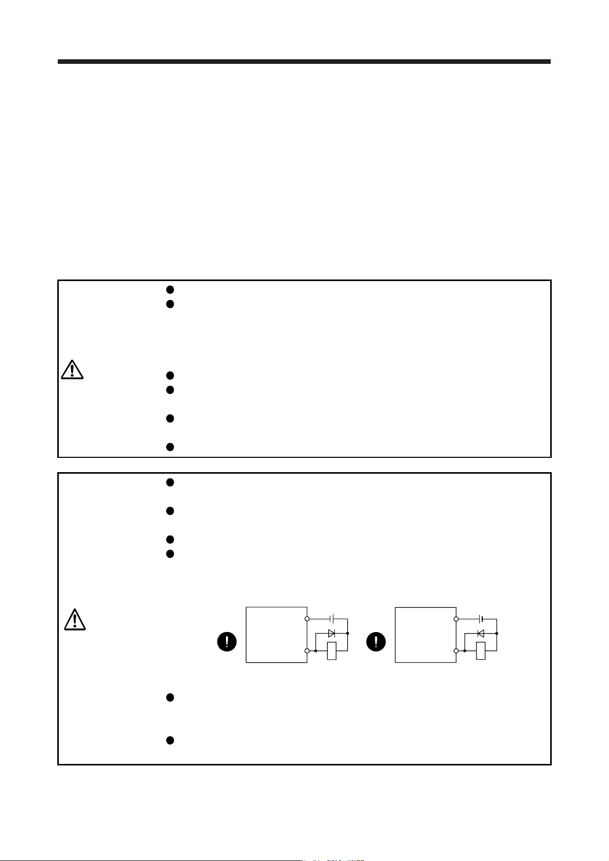
The surge absorbing diode installed to the DC relay for control output should be
fitted in the specified direction. Otherwise, the emergency stop and other
protective circuits may not operate.
DOCOM
24 V DC
Servo amplifier
RA
For sink output interface
Control output
signal
DOCOM
Control output
signal
24 V DC
Servo amplifier
RA
For source output interface
Use a noise filter, etc. to minimize the influence of electromagnetic interference.
Electromagnetic interference may be given to the electronic equipment used near
the servo amplifier.
Do not install a power capacitor, surge killer, or radio noise filter (FR-BIF option)
with the power wire of the direct drive motor.
15. USING A DIRECT DRIVE MOTOR
15 - 4
CAUTION
When using the regenerative resistor, switch power off with the alarm signal.
Otherwise, a transistor fault or the like may overheat the regenerative resistor,
causing a fire.
Do not modify the equipment.
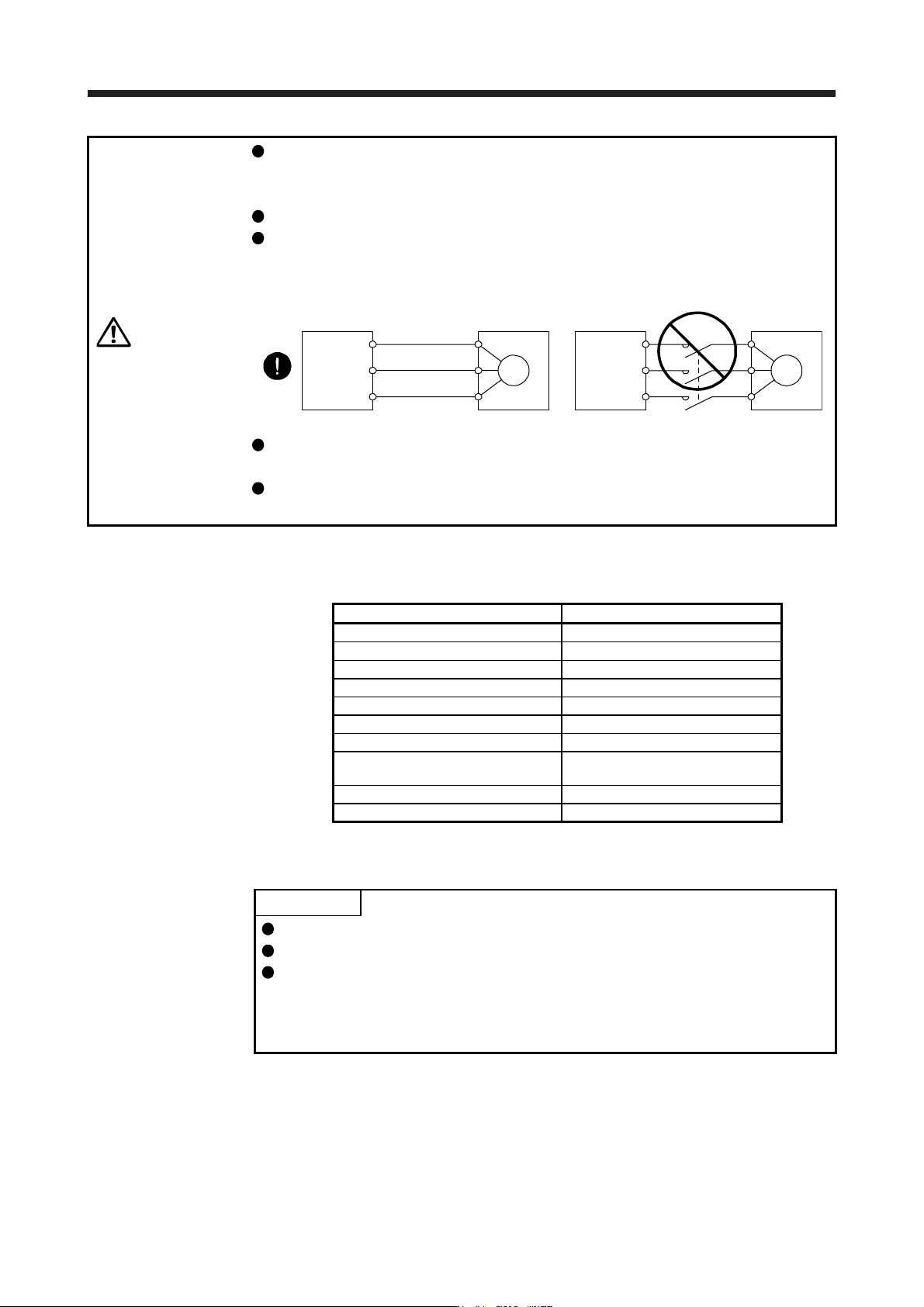
Connect the servo amplifier power output (U/V/W) to the power input of the direct
drive motor (U/V/W) directly. Do not let a magnetic contactor, etc. intervene.
Otherwise, it may cause a malfunction.
Servo amplifier Servo amplifier
Direct drive
motor
Direct drive
motor
U
M
V
W
U
V
W
U
M
V
W
U
V
W
Connecting a servo motor for different axis to the U, V, W, or CN2 may cause a
malfunction.
Before wiring, switch operation, etc., eliminate static electricity. Otherwise, it may
cause a malfunction.
This chapter does not describe the following items. For details of the items, refer to each section of the
detailed description field.
Item Detailed explanation
Input power supply circuit Section 3.1
Explanation of power supply system Section 3.3
Signal (device) explanations Section 3.5
Alarm occurrence timing chart Section 3.7
Interfaces Section 3.8
SSCNET III cable connection Section 3.9
Grounding Section 3.11
Switch setting and display of the servo
amplifier
Section 4.3
PARAMETERS Chapter 5
TROUBLESHOOTING Chapter 8
15.3 Operation and functions
POINT
When using the direct drive motor, set [Pr. PA01] to "_ _ 6 _".
For the test operation, refer to section 4.4.
The Z-phase pulse of the direct drive motor must be turned on after power-on.
When the machine configuration does not allow one or more revolution of the
direct drive motor, install the direct drive motor so that the Z-phase pulse can be
turned on.