sh030106u.pdf - 第518页
15. USIN G A DI REC T DRIV E MOTOR 15 - 15 15.3.4 Func tion (1) Servo contr ol error detect ion func tion POINT For the ser vo con trol er ror detect ion funct ion, the posit ion an d spee d dev iation error detections a…

15. USING A DIRECT DRIVE MOTOR
15 - 14
15.3.3 Operation from controller
To configure the absolute position detection system by using the direct drive motor, the battery and the
absolute position storage unit MR-BTAS01 are required.
(1) Operation method
For the incremental system, the magnetic pole detection is automatically performed at the first servo-on
after the power-on. For this reason, when performing the positioning operation, create the sequence
which surely confirms the servo-on status as the inter lock condition of the positioning command.
Also, some parameter settings and the home position return differ according to the controller type.
(2) Servo system controller setting
The following parameters will be enabled by cycling the servo amplifier power after the controller writes
the parameters to the servo amplifier.
Setting item
Setting
Motion controller
R_MTCPU/Q17_DSCPU
Simple motion module
RD77MS_/QD77MS_ /
LD77MS_
Parameter
Amplifier setting MR-J4-B DD
Motor setting Automatic setting
No.
(Note)
Symbol
Name
Initial
value
PA01 **STY Operation mode 1000h 1060h
PC01 *ERZ Error excessive alarm level 0
Set the items as required.
PC03 *ENRS Encoder output pulse selection 0000h
PL01 **LIT1
Linear servo motor/DD motor function
selection 1
0301h
PL04 *LIT2
Linear servo motor/DD motor function
selection 2
0003h
PL05 LB1 Position deviation error detection level 0
PL06 LB2 Speed deviation error detection level 0
PL07 LB3
Torque/thrust deviation error detection
level
100
PL08 *LIT3
Linear servo motor/DD motor function
selection 3
0010h
PL09 LPWM Magnetic pole detection voltage level 30
PL17 LTSTS
Magnetic pole detection - Minute
position detection method - Function
selection
0000h
PL18 IDLV
Magnetic pole detection - Minute
position detection method -
Identification signal amplitude
0
Note. The parameter whose symbol is preceded by * is enabled with the following conditions.
* : After setting the parameter, power off and on the servo amplifier or reset the controller.
**: After settin
g
the parameter, power off and on the servo amplifier.
15. USING A DIRECT DRIVE MOTOR
15 - 15
15.3.4 Function
(1) Servo control error detection function
POINT
For the servo control error detection function, the position and speed deviation
error detections are enabled by default. ([Pr. PL04]: _ _ _ 3)
If the servo control gets unstable for some reasons, the direct drive motor may not operate properly. To
detect this state and to stop operation, the servo control error detection function is used as a protective
function.
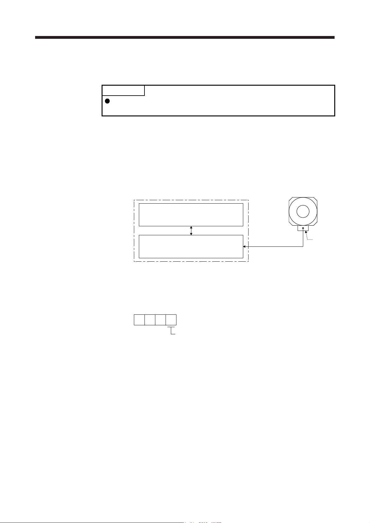
The servo control error detection function has three different detection methods: the position deviation,
speed deviation, and torque deviation. An error is detected when each method is enabled with [Pr. PL04
Linear servo motor/DD motor function selection 2]. The detection level can be changed with [Pr. PL05],
[Pr. PL06], and [Pr. PL07].
Servo amplifier internal value
1)
Model feedback position [rev]
3)
Model feedback speed [r/min]
5)
Command torque [%]
Encoder
2)
Feedback position [rev]
4)
Feedback speed [r/min]
6)
Feedback torque [%]
Servo amplifier
Direct drive motor
Encoder
Figure 15.1 Outline of servo control error detection function
(a) Position deviation error detection
Set [Pr. PL04] to "_ _ _ 1" to enable the position deviation error detection.
[Pr. PL04]
Position deviation error detection enabled
1
When you compare the model feedback position ( 1)) and the feedback position ( 2)) in figure 15.1, if
the deviation is more than the value of [Pr. PL05 Position deviation error detection level] (1 (0.01 rev)
to 1000 (10 rev)), [AL. 42.1 Servo control error by position deviation] will occur and the linear servo
motor will stop. The initial value of this detection level is 0.09 rev. Replace the set value as required.
15. USING A DIRECT DRIVE MOTOR
15 - 16
(b) Speed deviation error detection
Set [Pr. PL04] to "_ _ _ 2" to enable the speed deviation error detection.
[Pr. PL04]
Speed deviation error detection enable
d
2
When you compare the model feedback speed ( 3)) and the feedback speed ( 4)) in figure 15.1, if the
deviation is more than the value of [Pr. PL06 Speed deviation error detection level] (1 r/min to 2000
r/min), [AL. 42.2 Servo control error by speed deviation] will occur and the linear servo motor will
stop. The initial value of this detection level is 100 r/min. Replace the set value as required.
(c) Torque deviation error detection level
Set [Pr. PL04] to "_ _ _ 4" to enable the torque deviation error detection.
[Pr. PL04]
Torque deviation error detection enabled
4
When you compare the command torque ( 5)) and the feedback torque ( 6)) in figure 15.1, if the
deviation is more than the value of [Pr. PL07 Torque/thrust deviation error detection level] (1% to
1000%), [AL. 42.3 Servo control error by torque/thrust deviation] will occur and the linear servo motor
will stop. The initial value of this detection level is 100%. Replace the set value as required.
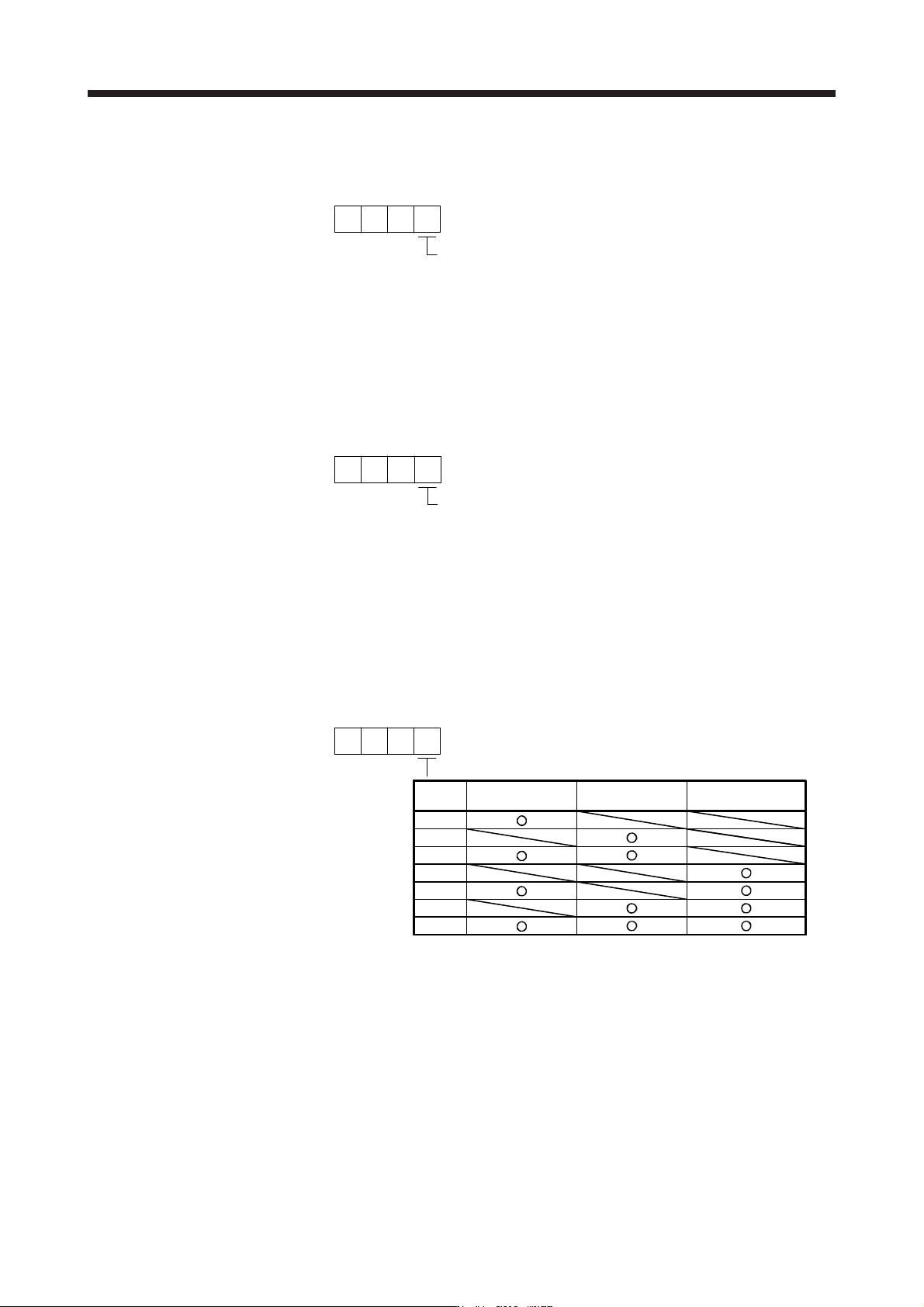
(d) Detecting multiple deviation errors
When setting [Pr. PL04] as shown below, multiple deviation errors can be detected. For the error
detection methods, refer to (1) (a), (b), (c) in this section.
[Pr. PL04]
Position deviation
error detection
Setting
value
Speed deviation
error detection
Torque deviation
error detection
1
5
6
7
3
2
4