sh030106u.pdf - 第524页
15. USIN G A DI REC T DRIV E MOTOR 15 - 21 (b) Dynamic brake t ime co nstant The foll owing sho ws neces sary dynamic br ake ti me cons tant τ for eq uation 15.1. Speed [r/min] 0 0 100 200 5 15 20 25 30 300 400 500 006 0…
15. USING A DIRECT DRIVE MOTOR
15 - 20
15.4.3 Dynamic brake characteristics
CAUTION
The coasting distance is a theoretically calculated value that does not consider
factors such as friction. The calculated distance is longer than the actual distance.
If the braking distance is not longer than the calculated value, a moving part may
crash into the stroke end, causing a dangerous situation. Install an anti-crash
mechanism such as an air brake or an electric/mechanical stopper such as a
shock absorber to reduce the shock of moving parts.
POINT
Do not use dynamic brake to stop in a normal operation as it is the function to
stop in emergency.
For a machine operating at the recommended load to motor inertia ratio or less,
the estimated number of usage times of the dynamic brake is 1000 times while
the machine decelerates from the rated speed to a stop once in 10 minutes.
Be sure to enable EM1 (Forced stop 1) after the direct drive motor stops when
using EM1 (Forced stop 1) frequently in other than emergency.
(1) Dynamic brake operation
(a) Calculation of coasting distance
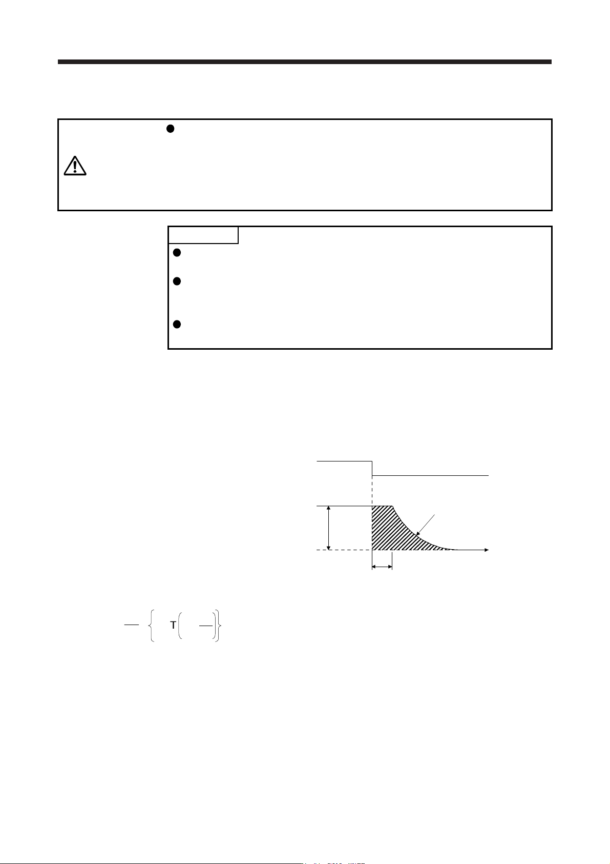
Fig. 15.3 shows the pattern in which the servo motor comes to a stop when the dynamic brake is
operated. Use equation 15.1 to calculate an approximate coasting distance to a stop. The dynamic
brake time constant τ varies with the direct drive motor and machine operation speeds. (Refer to (1)
(b) in this section.)
Dynamic brake
time constant τ
Time
t
e
V0
ON
OFF
EM1 (Forced stop 1)
Machine
speed
Fig. 15.3 Dynamic brake operation diagram
L
max
=
60
V
0
•
J
M
t
e
+1 +
J
L
······················································································ (15.1)
L
max
: Maximum coasting distance [mm]
V
0
: Machine's fast feed speed [mm/min]
J
M
: Moment of inertia of direct drive motor [kg•cm
2
]
J
L
: Load moment of inertia converted into equivalent value on direct drive motor rotor [kg•cm
2
]
τ: Dynamic brake time constant [s]
t
e
: Delay time of control section
There is internal relay delay time of about 10 ms.
[s]
15. USING A DIRECT DRIVE MOTOR
15 - 21
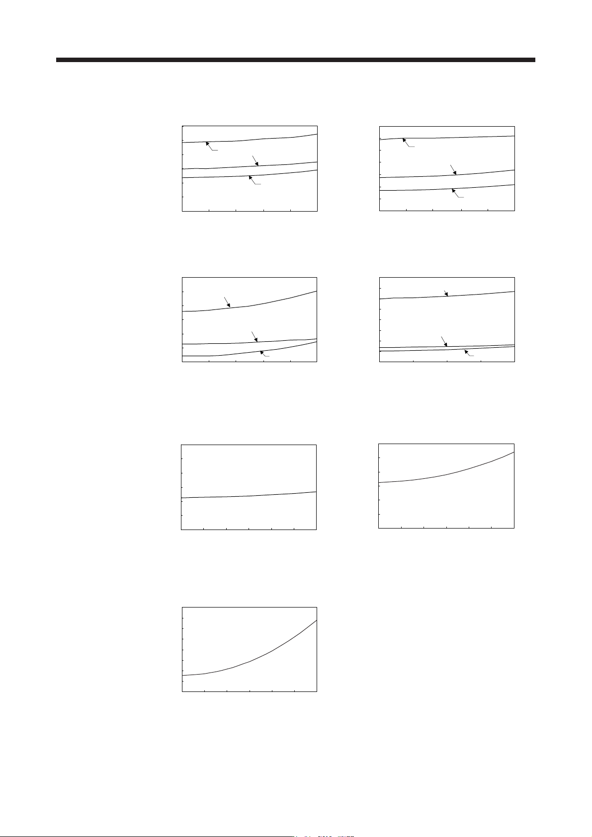
(b) Dynamic brake time constant
The following shows necessary dynamic brake time constant τ for equation 15.1.
Speed [r/min]
0
0 100 200
5
15
20
25
30
300 400 500
006
004
10
002
Time constant τ [ms]
0
0 100 200
70
300 400 500
012
006
018
10
20
30
40
50
60
Speed [r/min]
Time constant τ [ms]
TM-RFM_C20 TM-RFM_E20
0
0
10
30
40
50
60
20
100 200 300 400 500
Speed [r/min]
072
048
012
Time constant τ [ms]
0
0
60
50 100 150 200
70
80
50
40
30
20
10
Speed [r/min]
120
040
240
Time constant τ [ms]
TM-RFM_G20 TM-RFM_J10
0
0
25
30
20
15
10
5
0 100 200 300 400 500 600
Speed [r/min]
Time constant τ [ms]
0
0
5
15
20
25
30
10
0 100 200 300 400 500 600
Speed [r/min]
Time constant τ [ms]
TM-RG2M002C30
TM-RU2M002C30
TM-RG2M004E30
TM-RU2M004E30
0
0
60
70
80
50
40
30
20
10
0 100 200 300 400 500 600
Speed [r/min]
Time constant τ [ms]
TM-RG2M009G30
TM-RU2M009G30
15. USING A DIRECT DRIVE MOTOR
15 - 22
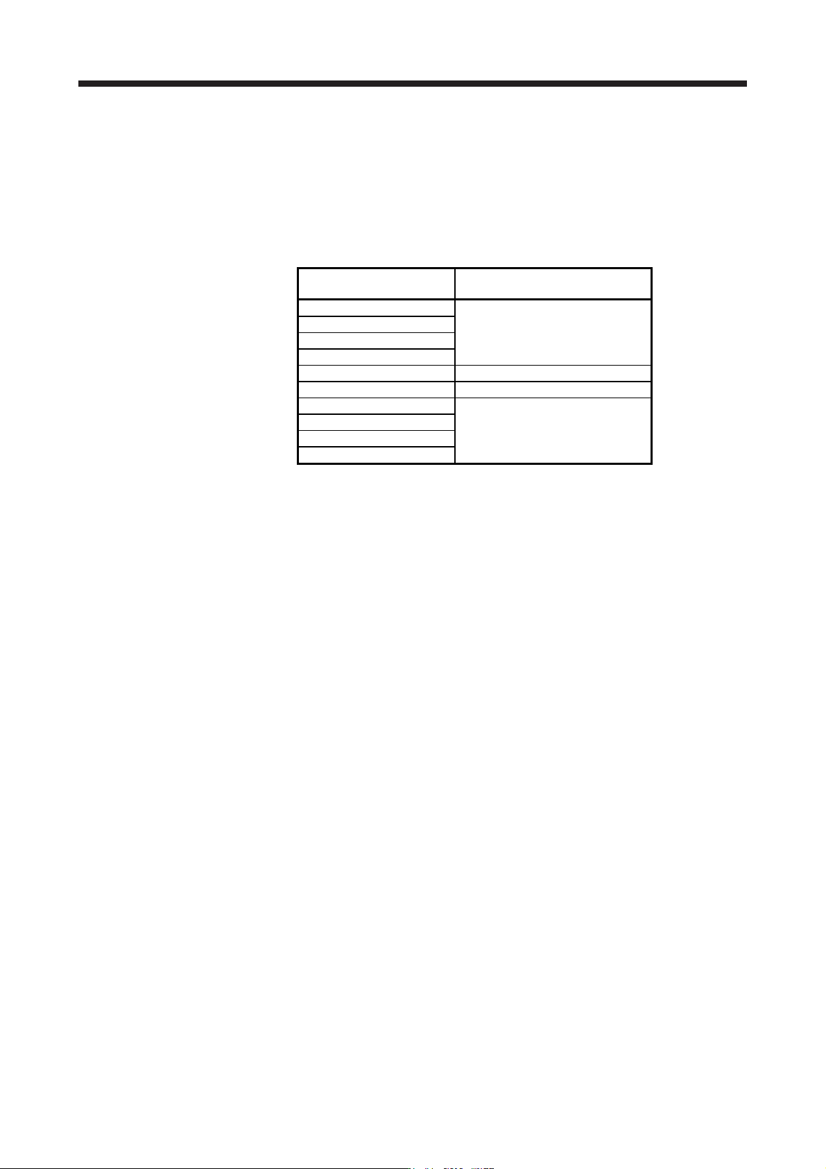
(2) Permissible load to motor inertia ratio when the dynamic brake is used
Use the dynamic brake under the load to motor inertia ratio indicated in the following table. If the load
inertia moment is higher than this value, the dynamic brake may burn. If the load to motor inertia ratio
exceeds the indicated value, contact your local sales office.
The values of the permissible load to motor inertia ratio in the table are the values at the maximum
rotation speed of the direct drive motor.
The value in the parenthesis shows the value at the rated speed of the direct drive motor.
Direct drive motor
Permissible load to motor inertia ratio
[multiplier]
TM-RFM_C20
100 (300)
TM-RFM_E20
TM-RG2M002C30
TM-RU2M002C30
TM-RFM_G20 50 (300)
TM-RFM_J10 50 (200)
TM-RG2M_E30
20 (80)
TM-RG2M_G30
TM-RU2M_E30
TM-RU2M_G30