sh030106u.pdf - 第525页
15. USIN G A DI REC T DRIV E MOTOR 15 - 22 (2) Permis sible load to motor iner tia rati o when t he dyna mic br ak e is us ed Use the dy namic br ake und er the load to mo tor iner tia r atio ind icated i n the fo llowin…
15. USING A DIRECT DRIVE MOTOR
15 - 21
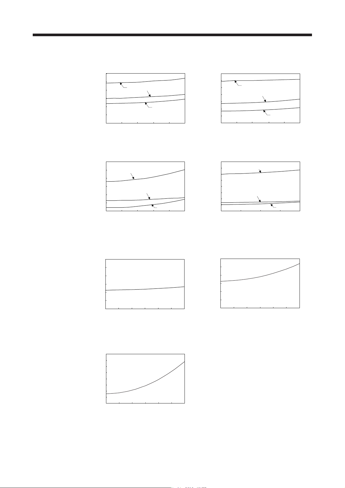
(b) Dynamic brake time constant
The following shows necessary dynamic brake time constant τ for equation 15.1.
Speed [r/min]
0
0 100 200
5
15
20
25
30
300 400 500
006
004
10
002
Time constant τ [ms]
0
0 100 200
70
300 400 500
012
006
018
10
20
30
40
50
60
Speed [r/min]
Time constant τ [ms]
TM-RFM_C20 TM-RFM_E20
0
0
10
30
40
50
60
20
100 200 300 400 500
Speed [r/min]
072
048
012
Time constant τ [ms]
0
0
60
50 100 150 200
70
80
50
40
30
20
10
Speed [r/min]
120
040
240
Time constant τ [ms]
TM-RFM_G20 TM-RFM_J10
0
0
25
30
20
15
10
5
0 100 200 300 400 500 600
Speed [r/min]
Time constant τ [ms]
0
0
5
15
20
25
30
10
0 100 200 300 400 500 600
Speed [r/min]
Time constant τ [ms]
TM-RG2M002C30
TM-RU2M002C30
TM-RG2M004E30
TM-RU2M004E30
0
0
60
70
80
50
40
30
20
10
0 100 200 300 400 500 600
Speed [r/min]
Time constant τ [ms]
TM-RG2M009G30
TM-RU2M009G30

15. USING A DIRECT DRIVE MOTOR
15 - 22
(2) Permissible load to motor inertia ratio when the dynamic brake is used
Use the dynamic brake under the load to motor inertia ratio indicated in the following table. If the load
inertia moment is higher than this value, the dynamic brake may burn. If the load to motor inertia ratio
exceeds the indicated value, contact your local sales office.
The values of the permissible load to motor inertia ratio in the table are the values at the maximum
rotation speed of the direct drive motor.
The value in the parenthesis shows the value at the rated speed of the direct drive motor.
Direct drive motor
Permissible load to motor inertia ratio
[multiplier]
TM-RFM_C20
100 (300)
TM-RFM_E20
TM-RG2M002C30
TM-RU2M002C30
TM-RFM_G20 50 (300)
TM-RFM_J10 50 (200)
TM-RG2M_E30
20 (80)
TM-RG2M_G30
TM-RU2M_E30
TM-RU2M_G30
16. FULLY CLOSED LOOP SYSTEM
16 - 1
16. FULLY CLOSED LOOP SYSTEM
POINT
The fully closed loop system is available for the servo amplifiers of which
software version is A3 or later.
When fully closed loop control system is used with this servo amplifier, "Linear
Encoder Instruction Manual" is needed.
Fully closed loop control system is available with position control mode.
When fully closed loop control system is configured with MR-J4-_B_ servo
amplifier, the following restrictions apply. However, these restrictions will not be
applied for MR-J4-_B_-RJ servo amplifiers.
A/B/Z-phase differential output type encoder cannot be used.
The load-side encoder and servo motor encoder is compatible with only the
two-wire type. The four-wire type load-side encoder and servo motor encoder
cannot be used.
When you use the KG-KR and HG-MR series for driving and load-side
encoder, the optional four-wire type encoder cables (MR-EKCBL30M-L, MR-
EKCBL30M-H, MR-EKCBL40M-H, and MR-EKCBL50M-H) cannot be used.
When an encoder cable of 30 m to 50 m is needed, fabricate a two-wire type
encoder cable according to app. 8.
The synchronous encoder Q171ENC-W8 can be used with servo amplifiers with
software version A8 or later.
16.1 Functions and configuration
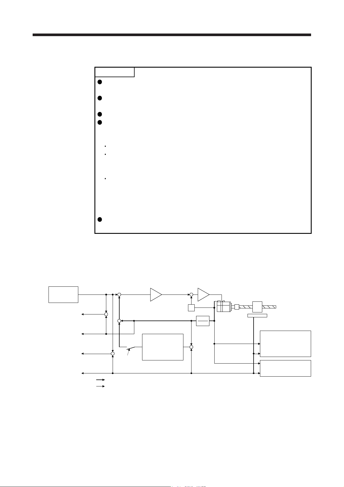
16.1.1 Function block diagram
A fully closed loop control block diagram is shown below. The fully closed loop system is controlled in the
load-side encoder unit.
Servo motor-side cumulative
feedback pulses
(load-side encoder resolution unit)
(Servo motor side)
Droop pulses
(Servo motor side)
Cumulative
feedback pulses
Load-side
droop pulses
Cumulative load-side
feedback pulses
Fully closed loop
dual feedback
filter
([Pr. PE08])
(Note 2)
FBD
Servo motor
Linear encoder
Controller
(Note 1, 2)
Fully closed loop selection
([Pr. PE01] and [Pr. PE08])
+
-
FBN
S
+
-
Encoder pulse setting
([Pr. PA15], [Pr. PA16]
and [Pr. PC03])
Fully closed loop control
error detection function
selection ([Pr. PE03])
+
-
+
+
-
+
-
+
Control
Monitor
Load-side feedback pulses
Note 1. Switching between semi closed loop control and fully closed loop control can be performed by changing the setting of [Pr.
PE01].
When semi closed loop control is selected, a control is always performed on the bases of the position data of the servo
motor encoder independently of whether the servo motor is at a stop or running.
2. When the fully closed loop system is enabled in [Pr. PE01], dual feedback control in which the servo motor feedback signal
and load-side encoder feedback signal are combined by the dual feedback filter in [Pr. PE08] is performed.
In this case, fully closed loop control is performed when the servo motor is at a stop, and semi closed loop control is
performed when the servo motor is operating to improve control performance. When "4500" is set as the filter value of [Pr.
PE08 Dual feedback filter], full
y
closed loop control is alwa
y
s performed.