sh030106u.pdf - 第538页
16. FULLY CLOSE D L OOP SYS TEM 16 - 13 (5) Setting of feed back pu lse elec tronic gear POINT If an incor rect va lue is set i n the fee dback p ulse elec tronic g ear ([Pr. PE04], [ Pr. PE05], [Pr . PE34], and [Pr . PE…
16. FULLY CLOSED LOOP SYSTEM
16 - 12
(3) Selection of load-side encoder communication method
The communication method changes depending on the load-side encoder type. Refer to table 1.1 and
"Linear Encoder Instruction Manual" for the communication method for each load-side encoder.
Select the cable to be connected to CN2L connector in [Pr. PC26].
000
[Pr. PC26]
Load-side encoder cable communication method selection
0: Two-wire type
1: Four-wire type
When using a load-side encoder of A/B/Z-phase differential output method, set "0".
Incorrect setting will trigger [AL. 70] and [AL. 71]. Setting "1" while
using a servo amplifier other than MR-J4-_B_-RJ will trigger [AL. 37].
(4) Setting of load-side encoder polarity
CAUTION
Do not set an incorrect direction to "Encoder pulse count polarity selection" in [Pr.
PC27]. An abnormal operation and a machine collision may occur if an incorrect
direction is set, which cause a fault and parts damaged.
POINT
"Encoder pulse count polarity selection" in [Pr. PC27] is not related to [Pr. PA14
Rotation direction selection]. Make sure to set the parameter according to the
relationships between servo motor and linear encoder/rotary encoder.
Do not set an incorrect direction to "Encoder pulse count polarity selection" in
[Pr. PC27]. Doing so may cause [AL. 42 Fully closed loop control error] during
the positioning operation.
(a) Parameter setting method
Set the load-side encoder polarity to be connected to CN2L connector in order to match the CCW
direction of servo motor and the increasing direction of load-side encoder feedback.
000
[Pr. PC27]
Encoder pulse count polarity selection
0: Load-side encoder pulse increasing direction in the servo motor CCW
1: Load-side encoder pulse decreasing direction in the servo motor CC
W
Servo motor
Linear encoder
Servo motor CCW direction
Address increasing direction of linear encoder
(b) How to confirm the load-side encoder feedback direction
For the way of confirming the load-side encoder feedback direction, refer to (6) in this section.
16. FULLY CLOSED LOOP SYSTEM
16 - 13
(5) Setting of feedback pulse electronic gear
POINT
If an incorrect value is set in the feedback pulse electronic gear ([Pr. PE04], [Pr.
PE05], [Pr. PE34], and [Pr. PE35]), [AL. 37 Parameter error] and an abnormal
operation may occur. Also, it may cause [AL. 42.8 Fully closed loop control error
by position deviation] during the positioning operation.
Set the electronic gear ([Pr. PE04], [Pr. PE34], [Pr. PE05], and [Pr. PE35]) for servo motor-side encoder
pulses. Set the electronic gear so that the number of servo motor encoder pulses per servo motor
revolution is converted to the number of load-side encoder pulses. The relational expression is shown
below.
Number of load-side encoder pulses per servo motor revolution
= Number of servo motor encoder pulses per servo motor revolution ×
[Pr. PE04] × [Pr. PE34]
[Pr. PE05] × [Pr. PE35]
Select the load-side encoder so that the number of load-side encoder pulses per servo motor revolution
is within the following range.
4096 (2
12
) ≤ Number of load-side encoder pulses per servo motor revolution ≤ 67108864 (2
26
)
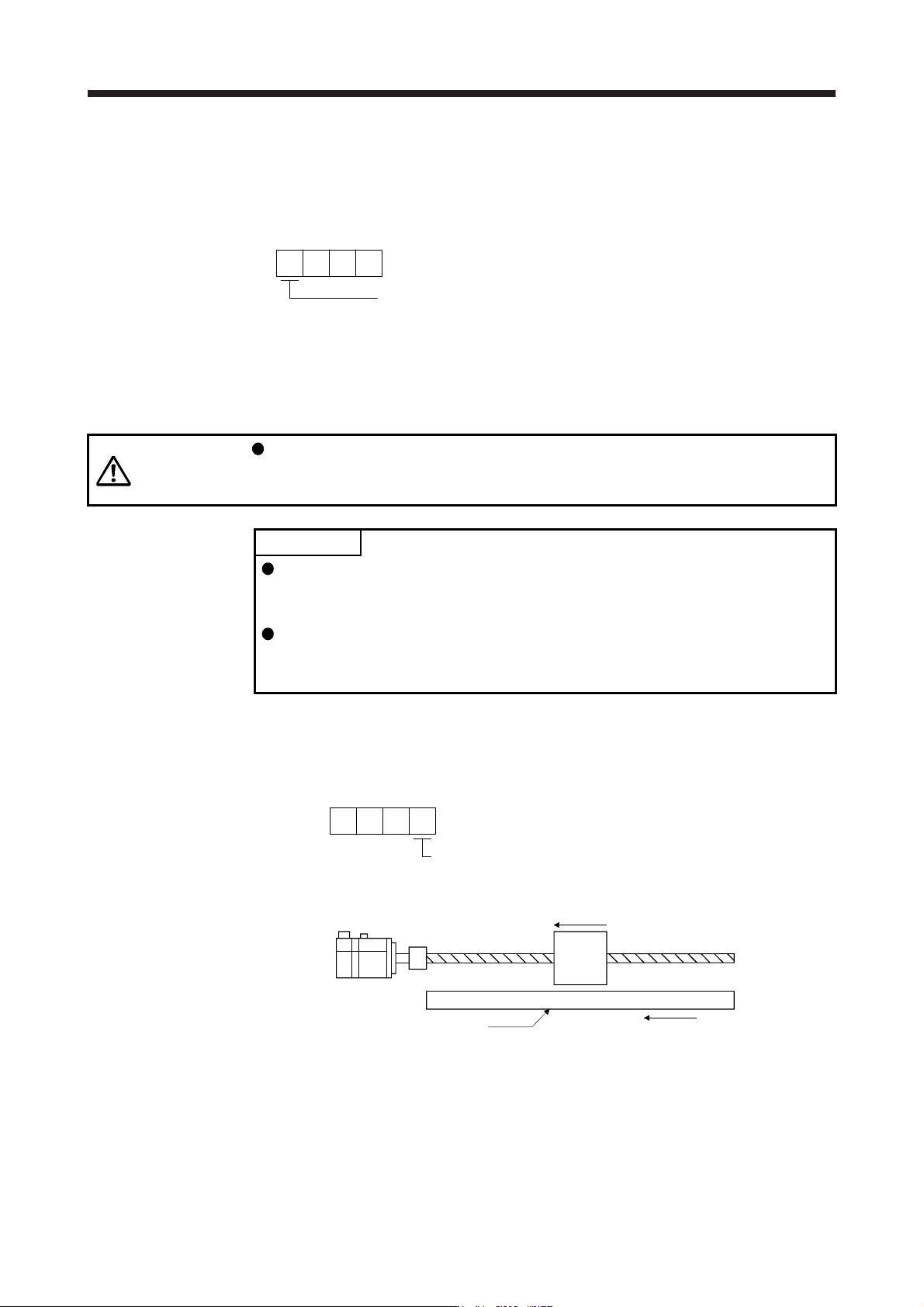
(a) When the servo motor is directly coupled with a ball screw and the linear encoder resolution is 0.05
μm
Conditions
Servo motor resolution: 4194304 pulses/rev
Servo motor reduction ratio: 1/11
Ball screw lead: 20 mm
Linear encoder resolution: 0.05 µm
Geared servo motor
Table
Linear encode
r
Linear encoder head
Calculate the number of linear encoder pulses per ball screw revolution.
Number of linear encoder pulses per ball screw revolution
= Ball screw lead/linear encoder resolution
= 20 mm/0.05 µm = 400000 pulses
[Pr. PE04] × [Pr. PE34]
[Pr. PE05] × [Pr. PE35]
400000
4194304
3125
32768
1
11
=
1
11
=
××
16. FULLY CLOSED LOOP SYSTEM
16 - 14
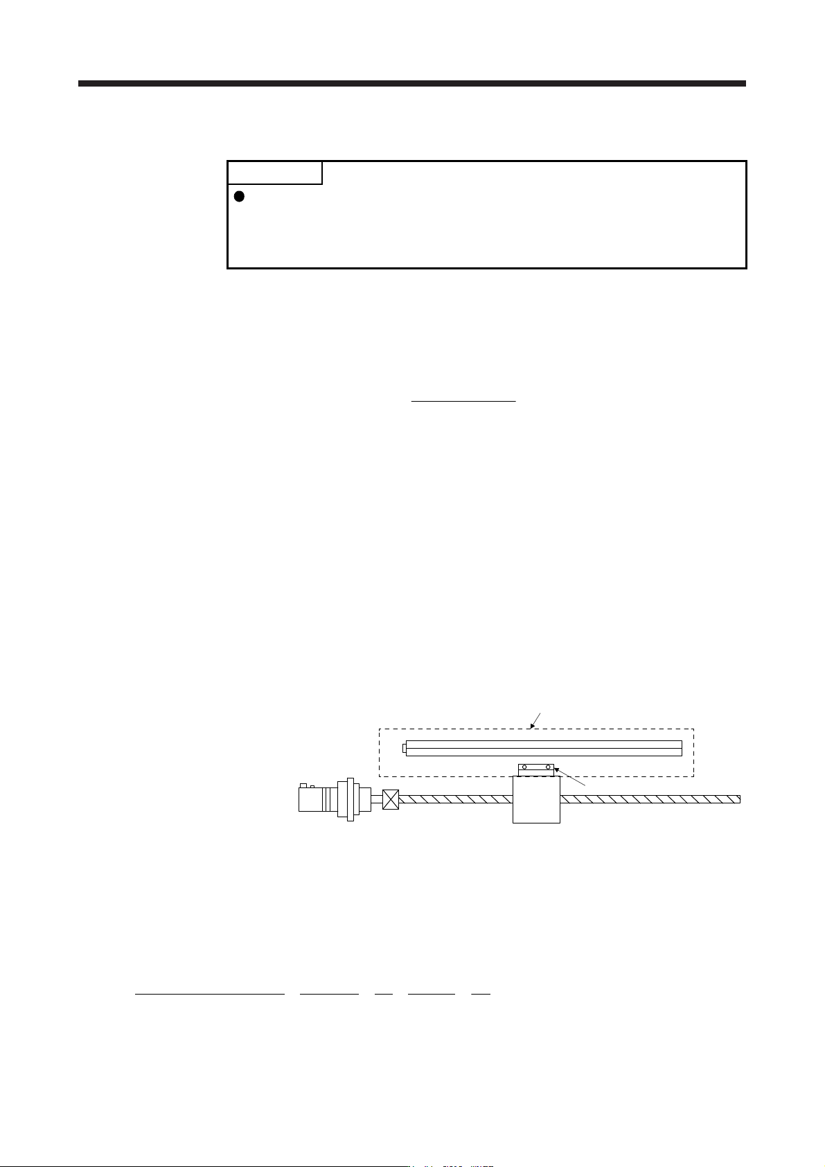
(b) Setting example when using the rotary encoder for the load-side encoder of roll feeder
Conditions
Servo motor resolution: 4194304 pulses/rev
Pulley diameter on the servo motor side: 30 mm
Pulley diameter on the rotary encoder side: 20 mm
Rotary encoder resolution: 4194304 pulse/rev
Servo motor
Rotary encoder
(HG-KR or HG-MR servo motor)
4194304 pulses/rev
Drive part
Pulley diameter
d1 = 30 mm
Pulley diameter
d2 = 20 mm
When the pulley diameters or reduction ratios differ, consider that in calculation.
=
[Pr. PE04] × [Pr. PE34]
[Pr. PE05] × [Pr. PE35]
4194304 × 20
1
1
4194304 × 30
=×
3
2