sh030106u.pdf - 第539页
16. FULLY CLOSE D L OOP SYS TEM 16 - 14 (b) Setting exam ple when us in g the rotary encoder for the load- side encod er of ro ll feeder Conditions Servo m otor reso lution: 419430 4 pulses /rev Pulley dia meter on the s…
16. FULLY CLOSED LOOP SYSTEM
16 - 13
(5) Setting of feedback pulse electronic gear
POINT
If an incorrect value is set in the feedback pulse electronic gear ([Pr. PE04], [Pr.
PE05], [Pr. PE34], and [Pr. PE35]), [AL. 37 Parameter error] and an abnormal
operation may occur. Also, it may cause [AL. 42.8 Fully closed loop control error
by position deviation] during the positioning operation.
Set the electronic gear ([Pr. PE04], [Pr. PE34], [Pr. PE05], and [Pr. PE35]) for servo motor-side encoder
pulses. Set the electronic gear so that the number of servo motor encoder pulses per servo motor
revolution is converted to the number of load-side encoder pulses. The relational expression is shown
below.
Number of load-side encoder pulses per servo motor revolution
= Number of servo motor encoder pulses per servo motor revolution ×
[Pr. PE04] × [Pr. PE34]
[Pr. PE05] × [Pr. PE35]
Select the load-side encoder so that the number of load-side encoder pulses per servo motor revolution
is within the following range.
4096 (2
12
) ≤ Number of load-side encoder pulses per servo motor revolution ≤ 67108864 (2
26
)
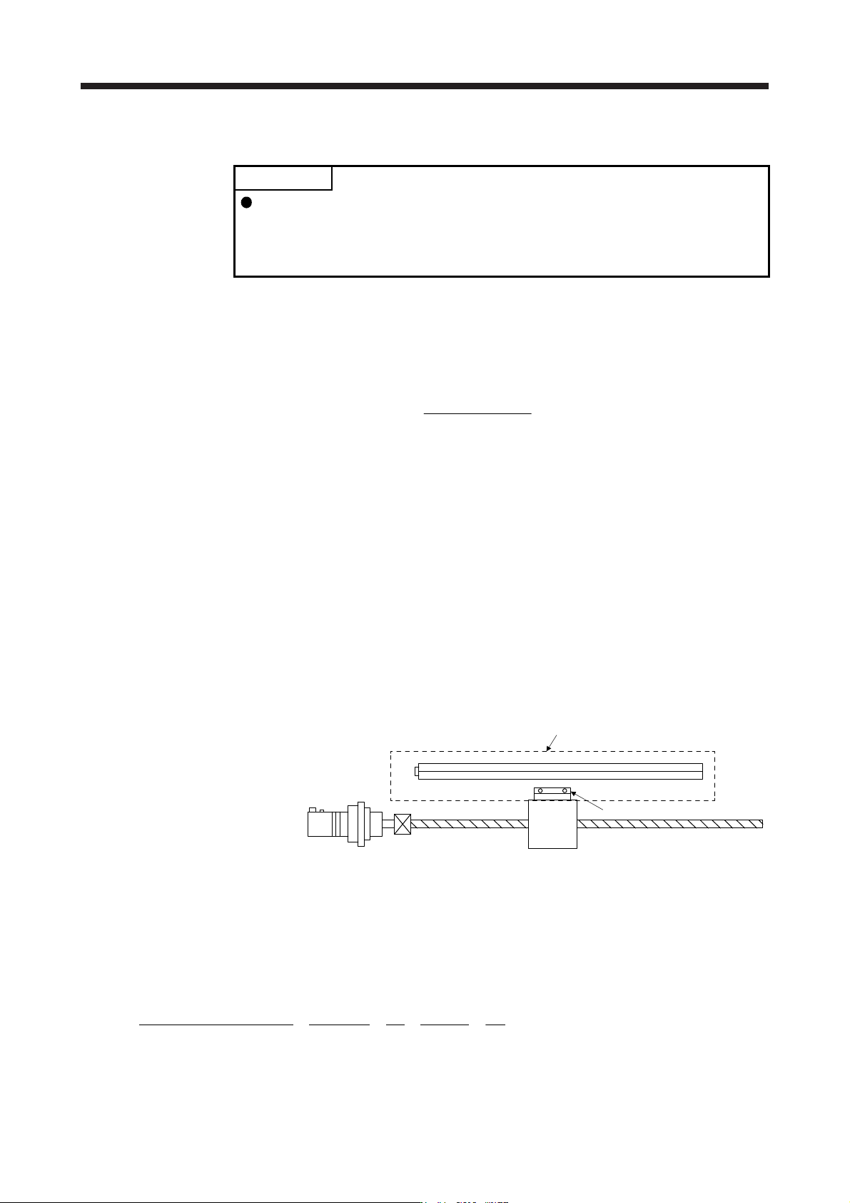
(a) When the servo motor is directly coupled with a ball screw and the linear encoder resolution is 0.05
μm
Conditions
Servo motor resolution: 4194304 pulses/rev
Servo motor reduction ratio: 1/11
Ball screw lead: 20 mm
Linear encoder resolution: 0.05 µm
Geared servo motor
Table
Linear encode
r
Linear encoder head
Calculate the number of linear encoder pulses per ball screw revolution.
Number of linear encoder pulses per ball screw revolution
= Ball screw lead/linear encoder resolution
= 20 mm/0.05 µm = 400000 pulses
[Pr. PE04] × [Pr. PE34]
[Pr. PE05] × [Pr. PE35]
400000
4194304
3125
32768
1
11
=
1
11
=
××
16. FULLY CLOSED LOOP SYSTEM
16 - 14
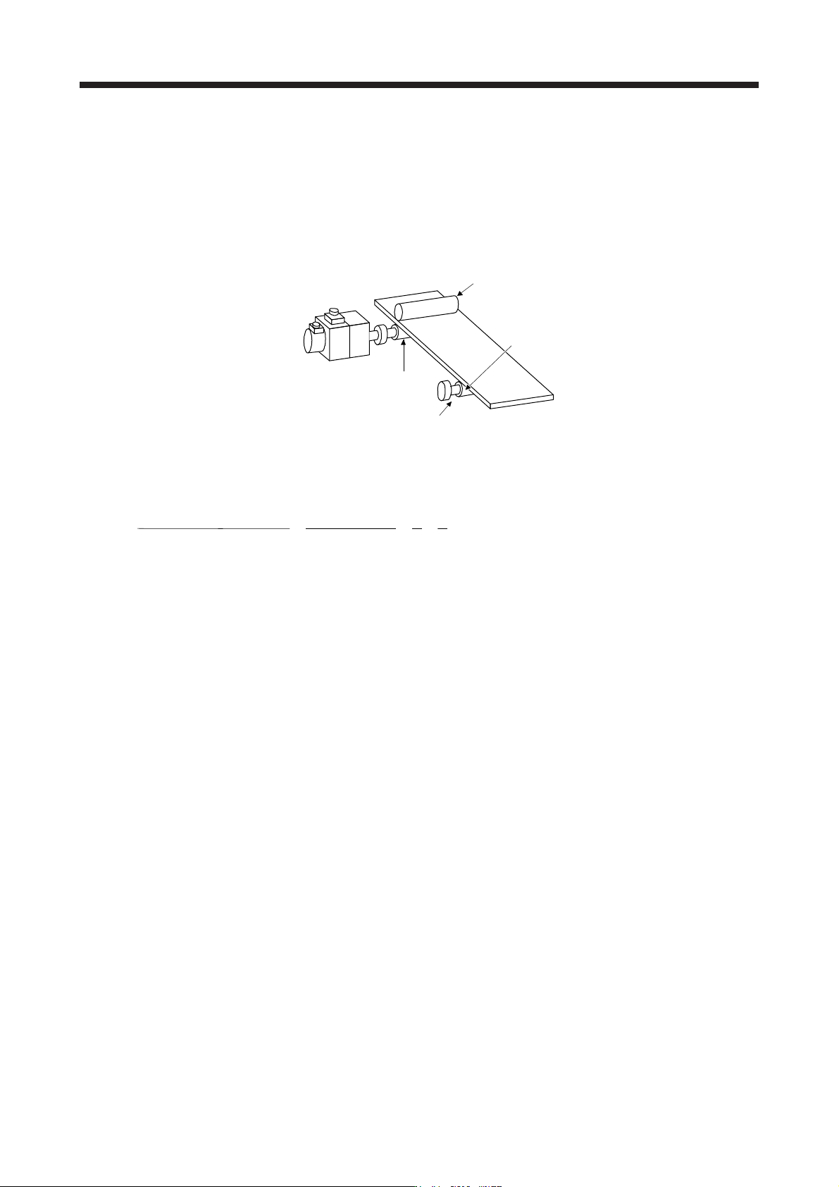
(b) Setting example when using the rotary encoder for the load-side encoder of roll feeder
Conditions
Servo motor resolution: 4194304 pulses/rev
Pulley diameter on the servo motor side: 30 mm
Pulley diameter on the rotary encoder side: 20 mm
Rotary encoder resolution: 4194304 pulse/rev
Servo motor
Rotary encoder
(HG-KR or HG-MR servo motor)
4194304 pulses/rev
Drive part
Pulley diameter
d1 = 30 mm
Pulley diameter
d2 = 20 mm
When the pulley diameters or reduction ratios differ, consider that in calculation.
=
[Pr. PE04] × [Pr. PE34]
[Pr. PE05] × [Pr. PE35]
4194304 × 20
1
1
4194304 × 30
=×
3
2
16. FULLY CLOSED LOOP SYSTEM
16 - 15
(6) Confirmation of load-side encoder position data
Check the load-side encoder mounting and parameter settings for any problems.
POINT
Depending on the check items, MR Configurator2 may be used.
Refer to section 16.3.9 for the data displayed on the MR Configurator2.
When checking the following items, the fully closed loop control mode must be set. For the setting of
control mode, refer to (2) in this section.
No. Check item Confirmation method and description
1
Read of load-side encoder position
data
With the load-side encoder in a normal state (mounting, connection, etc.), the load-side
cumulative feedback pulses value is counted normally when the load-side encoder is
moved.
1. An alarm occurred.
2. The installation of the load-side encoder was not correct.
3. The encoder cable was not wired correctly.
2
Read of load-side encoder home
position (reference mark, Z-phase)
With the home position (reference mark, or Z-phase) of the load-side encoder in a normal
condition (mounting, connection, etc.), the value of load-side encoder information 1 is
cleared to 0 when the home position (reference mark, or Z-phase) is passed through by
moving the load-side encoder.
1. The installation of the load-side encoder was not correct.
2. The encoder cable was not wired correctly.
3
Confirmation of load-side encoder
feedback direction
(Setting of load-side encoder
polarity)
Confirm that the directions of the cumulative feedback pulses of servo motor encoder (after
gear) and the load-side cumulative feedback pulses are matched by moving the device
(load-side encoder) manually in the servo-off status. If mismatched, reverse the polarity.
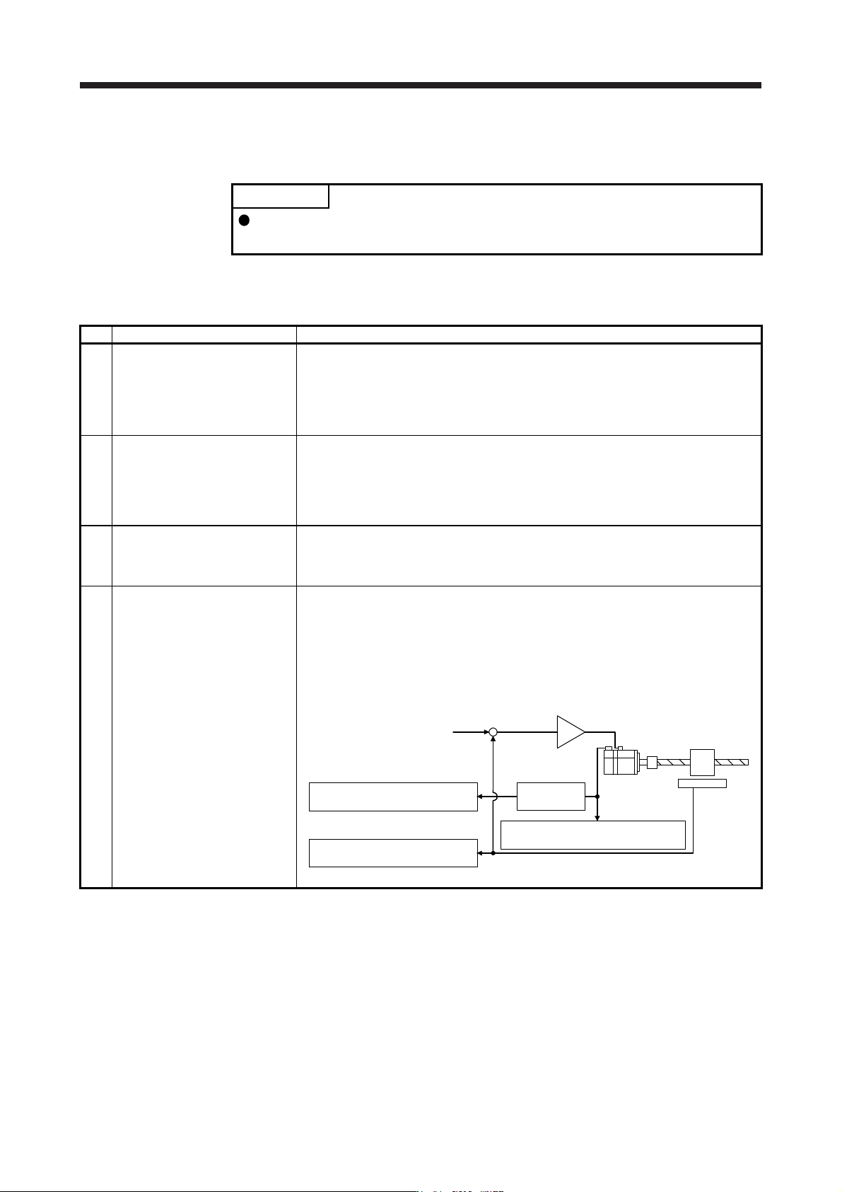
4
Setting of load-side encoder
electronic gear
When the servo motor and load-side encoder operate synchronously, the servo motor-side
cumulative feedback pulses (after gear) and load-side cumulative feedback pulses are
matched and increased.
If mismatched, review the setting of fully closed loop control feedback electronic gear ([Pr.
PE04], [Pr. PE05], [Pr. PE34], and [Pr. PE35]) with the following method.
1) Check the servo motor-side cumulative feedback pulses (before gear).
2) Check the load-side cumulative feedback pulses.
3) Check that the ratio of above 1) and 2) has been that of the feedback electronic gear.
Servo motor
Linear
encoder
+
-
Servo motor-side cumulative
feedback pulses (after gear)
3) Electronic
gear
2) Load-side cumulative
feedback pulses
Command
1) Servo motor-side cumulative
feedback pulses (before gear)