sh030106u.pdf - 第541页
16. FULLY CLOSE D L OOP SYS TEM 16 - 16 (7) Setting of ful ly closed loop dual fe edbac k filter With th e initia l value ( settin g = 10) s et in [ Pr. PE 08 Full y clos ed loop du al feed bac k filter the dua l feedbac…
16. FULLY CLOSED LOOP SYSTEM
16 - 15
(6) Confirmation of load-side encoder position data
Check the load-side encoder mounting and parameter settings for any problems.
POINT
Depending on the check items, MR Configurator2 may be used.
Refer to section 16.3.9 for the data displayed on the MR Configurator2.
When checking the following items, the fully closed loop control mode must be set. For the setting of
control mode, refer to (2) in this section.
No. Check item Confirmation method and description
1
Read of load-side encoder position
data
With the load-side encoder in a normal state (mounting, connection, etc.), the load-side
cumulative feedback pulses value is counted normally when the load-side encoder is
moved.
1. An alarm occurred.
2. The installation of the load-side encoder was not correct.
3. The encoder cable was not wired correctly.
2
Read of load-side encoder home
position (reference mark, Z-phase)
With the home position (reference mark, or Z-phase) of the load-side encoder in a normal
condition (mounting, connection, etc.), the value of load-side encoder information 1 is
cleared to 0 when the home position (reference mark, or Z-phase) is passed through by
moving the load-side encoder.
1. The installation of the load-side encoder was not correct.
2. The encoder cable was not wired correctly.
3
Confirmation of load-side encoder
feedback direction
(Setting of load-side encoder
polarity)
Confirm that the directions of the cumulative feedback pulses of servo motor encoder (after
gear) and the load-side cumulative feedback pulses are matched by moving the device
(load-side encoder) manually in the servo-off status. If mismatched, reverse the polarity.
4
Setting of load-side encoder
electronic gear
When the servo motor and load-side encoder operate synchronously, the servo motor-side
cumulative feedback pulses (after gear) and load-side cumulative feedback pulses are
matched and increased.
If mismatched, review the setting of fully closed loop control feedback electronic gear ([Pr.
PE04], [Pr. PE05], [Pr. PE34], and [Pr. PE35]) with the following method.
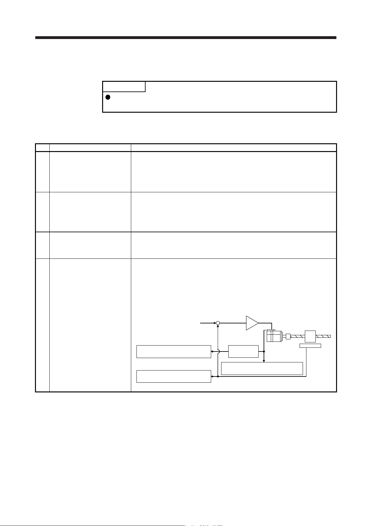
1) Check the servo motor-side cumulative feedback pulses (before gear).
2) Check the load-side cumulative feedback pulses.
3) Check that the ratio of above 1) and 2) has been that of the feedback electronic gear.
Servo motor
Linear
encoder
+
-
Servo motor-side cumulative
feedback pulses (after gear)
3) Electronic
gear
2) Load-side cumulative
feedback pulses
Command
1) Servo motor-side cumulative
feedback pulses (before gear)
16. FULLY CLOSED LOOP SYSTEM
16 - 16
(7) Setting of fully closed loop dual feedback filter
With the initial value (setting = 10) set in [Pr. PE08 Fully closed loop dual feedback filter the dual
feedback filter], make gain adjustment by auto tuning, etc. as in semi closed loop control. While
observing the servo operation waveform with the graph function, etc. of MR Configurator2, adjust the
dual feedback filter.
The dual feedback filter operates as described below depending on the setting.
[Pr. PE08] setting Control mode Vibration Settling time
0 Semi closed loop
1
to
4499
Dual feedback
Not frequently occurs
to
Frequently occurs
Long time
to
Short time
4500 Fully closed loop
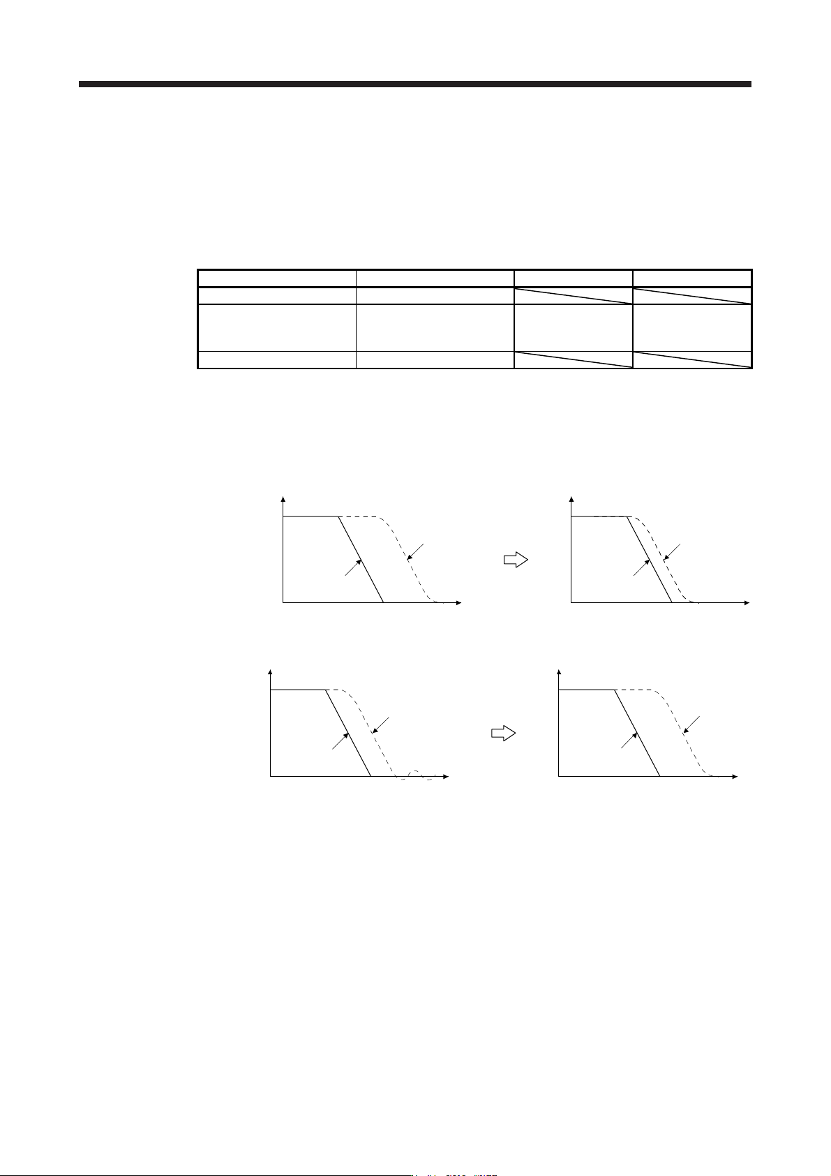
Increasing the dual feedback filter setting shortens the settling time, but increases servo motor vibration
since the motor is more likely to be influenced by the load-side encoder vibration. The maximum setting
of the dual feedback filter should be less than half of the PG2 setting.
Reduction of settling time: Increase the dual feedback filter setting.
Droop pulses
Command
Droop pulses
Command
TimeTime
Suppression of vibration: Decrease the dual feedback filter setting.
Droop pulses
Command
Droop pulses
Command
TimeTime
16. FULLY CLOSED LOOP SYSTEM
16 - 17
16.3.2 Home position return
(1) General instruction
Home position return is all performed according to the load-side encoder feedback data, independently
of the load-side encoder type. It is irrelevant to the Z-phase position of the servo motor encoder. In the
case of a home position return using a dog signal, the home position (reference mark) must be passed
through when an incremental type linear encoder is used, or the Z-phase be passed through when a
rotary encoder is used, during a period from a home position return start until the dog signal turns off.
(2) Load-side encoder types and home position return methods
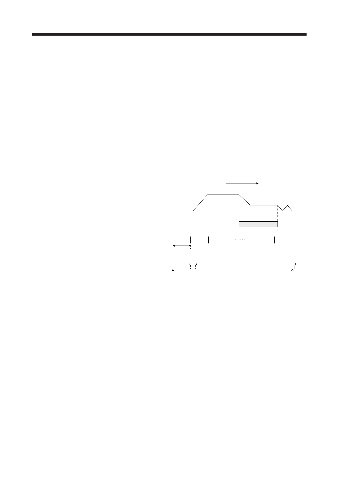
(a) About proximity dog type home position return using absolute type linear encoder
When an absolute type linear encoder is used, the home position reference position is the position
per servo motor revolution to the linear encoder home position (absolute position data = 0).
In the case of a proximity dog type home position return, the nearest position after proximity dog off
is the home position.
The linear encoder home position may be set in any position.
Linear encoder home position Home position
Home position return speed
Creep speed
Home position return direction
ON
OFF
Proximity dog
signal
Servo motor
speed
Reference home
position
Machine position
0 r/min
Equivalent to one servo motor revolution