sh030106u.pdf - 第544页
16. FULLY CLOSE D L OOP SYS TEM 16 - 19 If the home p osit ion return is performe d from the pos ition wh er e th e linear e ncode r home pos itio n (referenc e mark) does not exist, a home pos ition r eturn err or o ccu…
16. FULLY CLOSED LOOP SYSTEM
16 - 18
(b) About proximity dog type home position return using incremental linear encoder
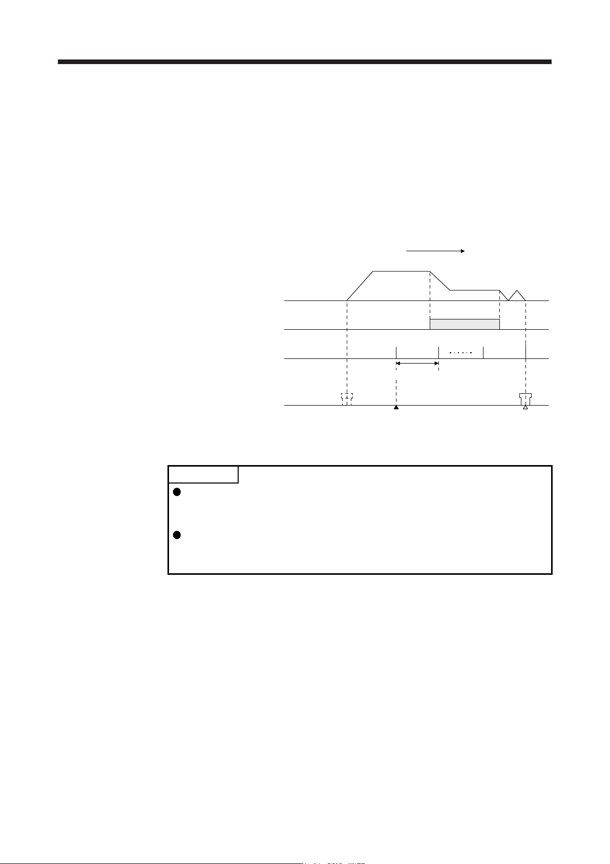
1) When the linear encoder home position (reference mark) exists in the home position return
direction
When an incremental linear encoder is used, the home position is the position per servo motor
revolution to the linear encoder home position (reference mark) passed through first after a home
position return start.
In the case of a proximity dog type home position return, the nearest position after proximity dog
off is the home position.
Set one linear encoder home position in the full stroke, and set it in the position that can always
be passed through after a home position return start.
Servo motor
speed
Linear encoder home position Home position
Home position return speed
Creep speed
Home position return direction
ON
OFF
Proximity dog
signal
Reference home
position
Machine position
Equivalent to one servo motor revolution
0 r/min
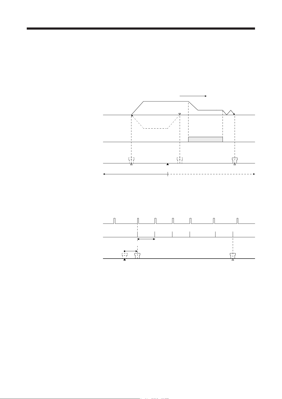
2) When the linear encoder home position does not exist in the home position return direction
POINT
To execute a home position return securely, start a home position return after
moving the axis to the opposite stroke end by jog operation, etc. of the
controller.
A home position return cannot be made if the incremental linear encoder does
not have a linear encoder home position (reference mark). Always provide a
linear encoder home position (reference mark). (one place in the fully stroke)
16. FULLY CLOSED LOOP SYSTEM
16 - 19
If the home position return is performed from the position where the linear encoder home position
(reference mark) does not exist, a home position return error occurs on the controller side. The
error contents differ according to the controller type. When starting a home position return at the
position where the linear encoder home position (reference mark) does not exist in the home
position return direction, move the axis up to the stroke end on the side opposite to the home
position return direction by JOG operation, etc. of the controller once, then make a home position
return.
Stroke end Home position
Home position return speed
Creep speed
Home position return direction
ON
OFF
Proximity dog
signal
Machine position
Linear encoder home position
JOG operation
Home position returnable area Home position non-returnable area
Servo motor
speed
0 r/min
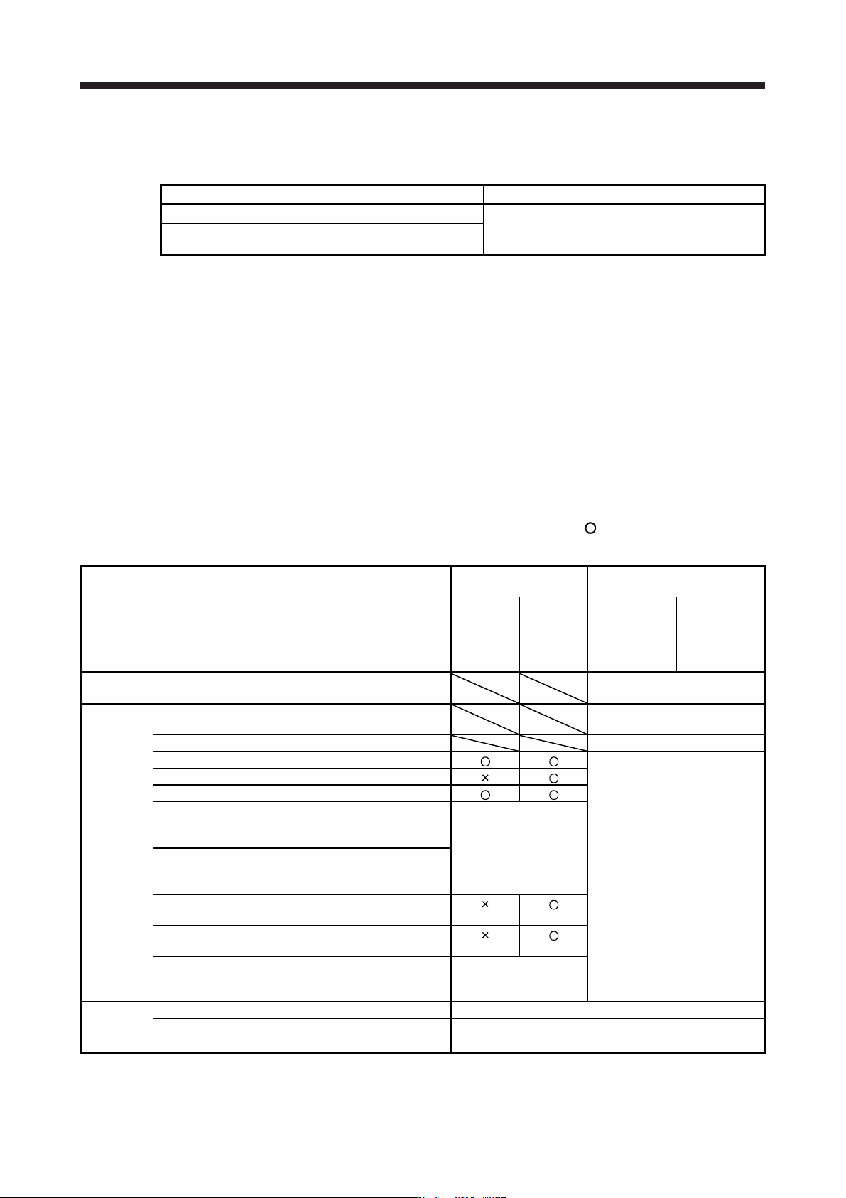
(c) About dog type home position return when using the rotary encoder of a serial communication servo
motor
The home position for when using the rotary encoder of a serial communication servo motor for the
load-side encoder is at the load-side Z-phase position.
Servo amplifier
power-on position
Home position
ON
OFF
Load-side encoder
Z-phase signal
Reference home position
Machine position
Equivalent to one servo motor revolution
(d) About data setting type (Common to all load-side encoders)
In the data setting type home position return method, pass through a home position (reference mark)
and the Z-phase signal of the rotary encoder, and then make a home position return.
When the machine has no distance of one servo motor encoder revolution until the Z-phase of the
rotary encoder is passed through, a home position return can be made by changing the home
position setting condition selection in [Pr. PC17] if the home position is not yet passed through.
16. FULLY CLOSED LOOP SYSTEM
16 - 20
16.3.3 Operation from controller
The fully closed loop control compatible servo amplifier can be used with any of the following controllers.
Category Model Remark
Motion controller R_MTCPU/Q17_DSCPU
Speed control (II) instructions (VVF and VVR) cannot
be used.
Simple motion module
RD77MS_/QD77MS_ /
LD77MS_
An absolute type linear encoder is necessary to configure an absolute position detection system under fully
closed loop control using a linear encoder. In this case, the encoder battery need not be installed to the
servo amplifier. When an rotary encoder is used, an absolute position detection system can be configured by
installing the encoder battery to the servo amplifier. In this case, the battery life will be shorter because the
power consumption is increased as the power is supplied to the two encoders of motor side and load side.
(1) Operation from controller
Positioning operation from the controller is basically performed like the semi closed loop control.
(2) Servo system controller setting
When using fully closed loop system, make the following setting.
[Pr. PA01], [Pr. PC17], [Pr. PE01], [Pr. PE03] to [Pr. PE05], [Pr. PE34] and [Pr. PE35] are written to the
servo amplifier and then are enabled using any of the methods indicated by
in Parameter enabled
conditions. [Pr. PE06] to [Pr. PE08] are enabled at setting regardless of the valid conditions.
Setting item
Parameter enabled
conditions
Settings
Controller
reset
Power
supply
Off→on
Motion
controller
R_MTCPU/
Q17_DSCPU
Simple motion
module
RD77MS_/
QD77MS_ /
LD77MS_
Command
resolution
Load-side encoder resolution
unit
Servo
parameter
MR-J4-B fully closed loop servo amplifier setting
MR-J4-B(-RJ) fully closed loop
control
Motor setting Automatic setting
Home position setting condition selection ([Pr. PC17])
Set the items as required.
Fully closed loop selection ([Pr. PA01] and [Pr. PE01])
Fully closed loop selection 2 ([Pr. PE03])
Fully closed loop control error detection speed deviation
error detection level
([Pr. PE06])
Enabled at setting
regardless of the
enabled conditions
Fully closed loop control error detection position
deviation error detection level
([Pr. PE07])
Fully closed loop electronic gear numerator ([Pr. PE04]
and [Pr. PE34])
Fully closed loop electronic gear denominator ([Pr. PE05]
and [Pr. PE35])
Fully closed loop dual feedback filter ([Pr. PE08])
Enabled at setting
regardless of the
enabled conditions
Positioning
control
parameter
Unit setting mm/inch/degree/pulse
Number of pulses per revolution (AP)
Travel distance per revolution (AL)
For the setting methods, refer to (2) (a), (b) in this section.