sh030106u.pdf - 第547页
16. FULLY CLOSE D L OOP SYS TEM 16 - 22 16.3.4 Fu lly clos ed loop co ntrol er ror det ection fu nctio ns If fully c losed l oop contro l becomes unstab le for s ome reason, t he speed at serv o motor s ide may incr ease…
16. FULLY CLOSED LOOP SYSTEM
16 - 21
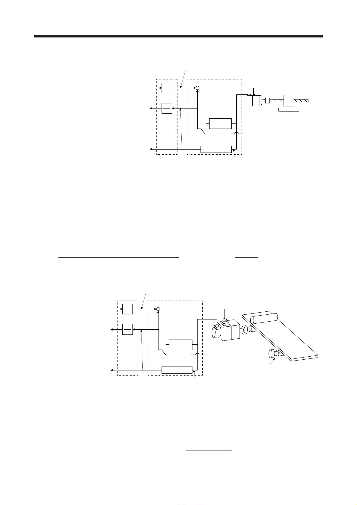
(a) When using a linear encoder (unit setting: mm)
Differentiation
AP
AL
Servo motor Linear encoder
Position feedback
[mm]
Command
[mm]
+
-
Speed feedback
[r/min]
AL
AP
Electronic
gear
User Control
Servo amplifier
Load-side encoder resolution unit
Load-side encoder
resolution unit
Servo motor speed
Calculate the number of pulses (AP) and travel distance (AL) of the linear encoder per ball screw
revolution in the following conditions.
Ball screw lead: 20 mm
Linear encoder resolution: 0.05 µm
Number of linear encoder pulses (AP) per ball screw revolution
= Ball screw lead/linear encoder resolution = 20 mm/0.05 µm = 400000 pulses
Number of pulses per revolution [pulse] (AP)
Travel distance per revolution [µm] (AL)
=
400000 pulses
20 mm
=
400000
20000
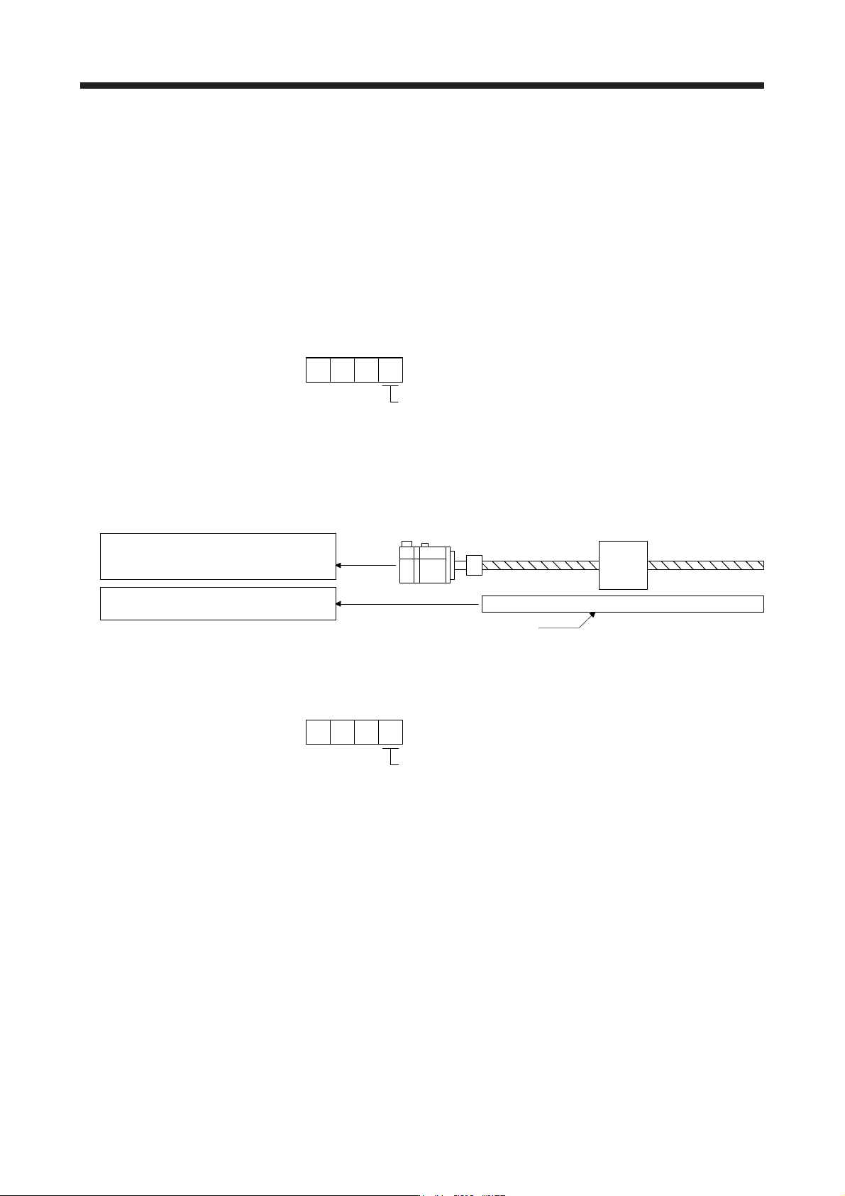
(b) When using a rotary encoder (unit setting: degree)
Servo motor
Rotary encoder
(HG-KR or HG-MR servo motor)
4194304 pulses/rev
AP
AL
Position feedback
[degree]
Command
[degree]
+
-
Speed feedback
[r/min]
AL
AP
Electronic
gear
User Control Servo amplifier
Load-side encoder resolution unit
Load-side encoder
resolution unit
Servo motor speed
Differentiation
Calculate the number of pulses (AP) and travel distance (AL) of the rotary encoder per servo motor
revolution in the following conditions.
Resolution of rotary encoder = Load-side resolution: 4194304 pulses/rev
Number of pulses per revolution [pulse] (AP)
Travel distance per revolution [degree] (AL)
=
4194304 pulses
360 degrees
=
524288
45
16. FULLY CLOSED LOOP SYSTEM
16 - 22
16.3.4 Fully closed loop control error detection functions
If fully closed loop control becomes unstable for some reason, the speed at servo motor side may increase
abnormally. The fully closed loop control error detection function is a protective function designed to pre-
detect it and stop operation.
The fully closed loop control error detection function has two types of detection methods: speed deviation
and position deviation. Select a detection method with [Pr. PE03 Fully closed loop function selection 2].
The detection level setting can be changed using [Pr. PE06] and [Pr. PE07].
(1) Parameter
The fully closed loop control error detection function is selected.
Fully closed loop control error detection function
0: Disabled
1: Speed deviation error detection
2: Position deviation error detection
3: Speed deviation error, position deviation error detectio
n
(Initial value)
[Pr. PE03]
(2) Fully closed loop control error detection functions
Servo motor
Linear encoder
1) Servo motor-side feedback speed [r/min]
2) Servo motor-side feedback position [pulse]
(load side equivalent value)
3) Load-side feedback speed [r/min]
4) Load-side feedback position [pulse]
(a) Speed deviation error detection
Set [Pr. PE03] to "_ _ _ 1" to enable the speed deviation error detection.
Speed deviation error detectio
n
1
[Pr. PE03]
The function compares the servo motor-side feedback speed (1)) and load-side feedback speed (3)).
If the deviation is not less than the set value (1 r/min to the permissible speed) of [Pr. PE06 Fully
closed loop control speed deviation error detection level], the function generates [AL. 42.2 Servo
control error by speed deviation] and stops. The initial value of [Pr. PE06] is 400 r/min. Change the
set value as required.
16. FULLY CLOSED LOOP SYSTEM
16 - 23
(b) Position deviation error detection
Set [Pr. PE03] to "_ _ _ 2" to enable the position deviation error detection.
Position deviation error detectio
n
2
[Pr. PE03]
Comparing the servo motor-side feedback position (2)) and load-side feedback position (4)), if the
deviation is not less than the set value (1 kpulses to 20000 kpulses) of [Pr. PE07 Fully closed loop
control position deviation error detection level], the function generates [AL. 42.1 Servo control error
by position deviation] and stops. The initial value of [Pr. PE07] is 100 kpulses. Change the set value
as required.
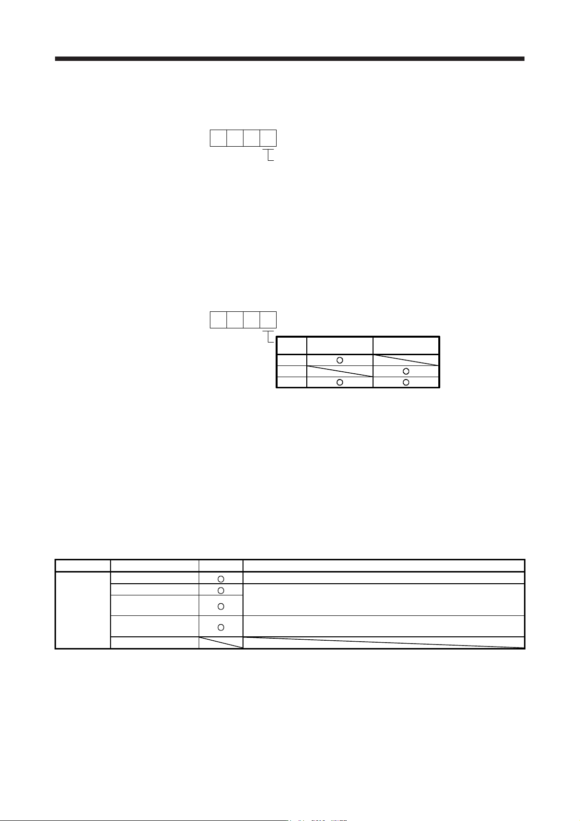
(c) Detecting multiple deviation errors
When setting [Pr. PE03] as shown below, multiple deviation errors can be detected. For the error
detection method, refer to (2) (a), (b) in this section.
[Pr. PE03]
Setting
value
Speed deviation
error detection
Position deviation
error detection
1
2
3
16.3.5 Auto tuning function
Refer to section 6.3 for the auto tuning function.
16.3.6 Machine analyzer function
Refer to Help of MR Configurator2 for the machine analyzer function of MR Configurator2.
16.3.7 Test operation mode
Test operation mode is enabled by MR Configurator2.
For details on the test operation mode, refer to section 4.5.
Function Item Usability Remark
Test
operation
mode
JOG operation
It drives in the load-side encoder resolution unit
Positioning operation
The fully closed loop system is operated in the load-side encoder resolution
unit.
For details, refer to section 4.5.1 (1) (c).
Program operation
Output signal (DO)
forced output
Refer to section 4.5.1 (1) (d).
Motor-less operation