sh030106u.pdf - 第555页
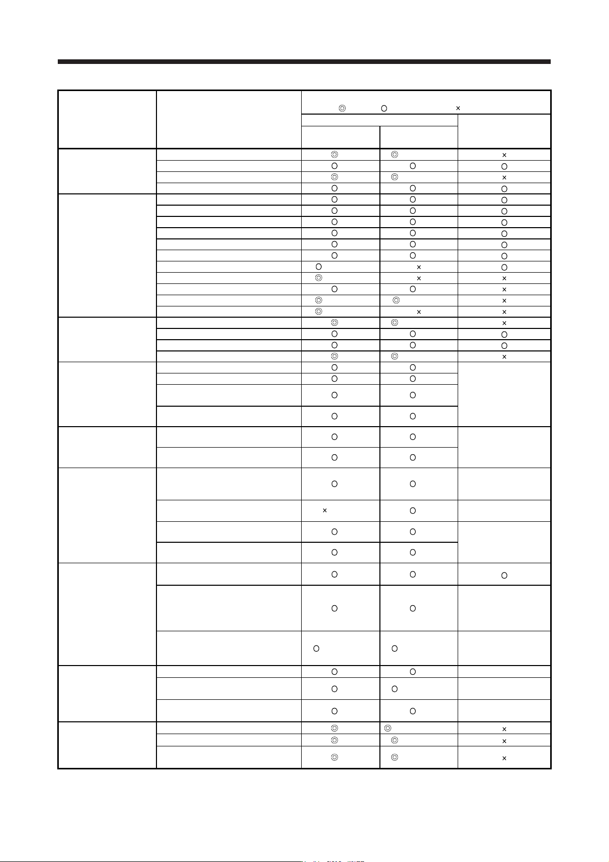
17. APPLICATIO N OF FUNCTIONS 17 - 4 Compatib ility ( : J4 n ew, : Equival ent to J3, : Not available) Function Name MR-J4 series MR-J3/MR-J3W s eries (Note 8) J 4 mode J3 compatibil ity mode 3-dig it alarm d isplay A0 A…
17. APPLICATION OF FUNCTIONS
17 - 3
Compatibility
(
: J4 new, : Equivalent to J3, : Not available)
Function Name MR-J4 series
MR-J3/MR-J3W series
(Note 8)
J4 mode
J3 compatibility
mode
Standard mode/3 inertia mode A0 B0 (Note 15)
Vibration suppression
control
Vibration suppression control 1
A0 A0
Vibration suppression control 2 A0 B0 (Note 15)
Command notch filter A0 A0
Gain switching A0 A0
Slight vibration suppression control A0 A0
Overshoot amount compensation A0 A0
PI-PID switching control A0 A0
Feed forward A0 A0
Applied control Torque limit A0 A0
Master-slave operation function A8 (Note 5)
Scale measurement function A8 (Note 3)
Model adaptive control disabled B4 B4
Lost motion compensation function B4 (Note 5) (Note 5, 15)
Super trace control B4 (Note 5)
One-touch tuning A0 B0 (Note 15)
Adjustment function
Adaptive tuning
A0 A0
Vibration suppression control 1 tuning A0 A0
Vibration suppression control 2 tuning A0 B0 (Note 15)
Fully closed loop electronic gear A3 A3
Dual feedback control A3 A3
Fully closed loop control
Semi closed/fully closed switching
loop control
A3 A3
MR-J3-_S
MR-J3-_B-RJ006
Fully closed loop control error
detection function
A3 A3
Linear compatible
Linear servo control error detection
function
A0 A0
MR-J3-_B-RJ004
MR-J3W-_B
Servo motor series/types setting
function
A0 A0
Magnetic pole detection
Direct current exciting method
magnetic pole detection
A0 A0
MR-J3-_B-RJ004
MR-J3-_B-RJ080W
MR-J3W-_B
Current detection method magnetic
pole detection
(Note 6) A0
MR-J3-_B-RJ004
MR-J3W-_B
Minute position detection method
magnetic pole detection
A0 A0
MR-J3-_B-RJ004
MR-J3-_B-RJ080W
MR-J3W-_B
Initial magnetic pole detection error
detection function
A0 A0
Encoder
Semi closed loop control two-wire
type/four-wire type selection
A0 A0
Serial interface compatible linear
encoder
A0 A0
MR-J3-_S
MR-J3-_B-RJ006
MR-J3-_B-RJ004
MR-J3W-_B
Pulse train interface (A/B/Z-phase
differential output type) compatible
linear encoder
A5 (Note 14) A5 (Note 14)
MR-J3-_S
MR-J3-_B-RJ006
MR-J3-_B-RJ004
Functional safety
STO function
A0 A0 MR-J3-_S
Forced stop deceleration function at
alarm occurrence
A0 A0 (Note 12) MR-J3-_S
Vertical axis freefall prevention
function
A0 A0 MR-J3-_S
Tough drive function
SEMI-F47 function
A0 B0 (Note 15, 16)
Vibration tough drive A0 B0 (Note 15)
Instantaneous power failure tough
drive
A0 B0 (Note 15)
17. APPLICATION OF FUNCTIONS
17 - 4
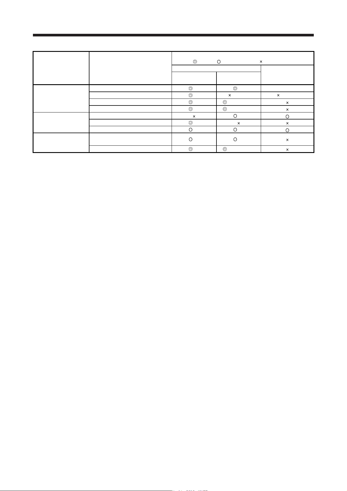
Compatibility
(
: J4 new, : Equivalent to J3, : Not available)
Function Name MR-J4 series
MR-J3/MR-J3W series
(Note 8)
J4 mode
J3 compatibility
mode
3-digit alarm display A0 A0 MR-J3W-_B
Diagnosis function
16 alarm histories supported
A0 (Note 7) (Note 7)
Drive recorder function A0 B0 (Note 15)
Machine diagnosis function A0 B0 (Note 15)
SSCNET III A0
Controller SSCNET III/H A0
Home position return function A0 A0
Others
J4 mode/J3 compatibility mode
automatic identification (Note 11)
A0 A0
Power monitoring function A0 B0 (Note 15)
Note 1. The value is at the HG series servo motor driving. The resolution of the linear encoder/direct drive motor is the same both in
the J4 mode and J3 compatibilit
y
mode. Refer to the instruction manual.
2. The motor-less operation cannot be used in the fully closed loop control mode, linear servo motor control mode, or DD motor
control mode.
3. It is not available with MR-J4W3-
_
B servo amplifiers.
4. It is not available with the MR-J3W-
_
B, MR-J4W2-
_
B, and MR-J4W3-
_
B servo amplifiers.
5. It is not available with the MR-J4W2-
_
B and MR-J4W3-
_
B servo amplifiers.
6. The minute position detection method is available instead.
7.
A
larm histor
y
will be saved up to six times.
8. The functions of the product with modified parts (GA) in the MR-J3-_B servo amplifiers are all covered by the J3 compatibility
mode of the MR-J4-
_
B servo amplifiers.
9. MR-J4W3-
_
B servo amplifiers do not support the full
y
closed loop control s
y
stem.
10. For MR-J4 series, the robust filter and vibration tou
g
h drive are available instead.
11. The operation mode will be identified automatically at the first controller communication. To switch the operation mode, use the
application "MR-J4
(
W
)
-B mode selection" or "MR Mode Chan
g
e".
12. When MR-J4 is used as a replacement of MR-J3-_S, "Servo forced stop selection" in [Pr. PA04] will be "Disabled (_ 1 _ _)" in
the initial settin
g
. Chan
g
e the settin
g
as necessar
y
.
13. This is for MR-J4-_B servo amplifier. MR-J4-_B-RJ servo amplifier is compatible with two-wire type, four-wire type, and A/B/Z-
phase differential output method.
14. It is available with onl
y
MR-J4-
_
B-RJ servo amplifiers. It is not available with MR-J4-
_
B servo amplifiers.
15. This is available when the J3 extension function is enabled. Refer to section 17.1.9 for details.
16. For servo s
y
stem controllers which are available with this, contact
y
our local sales office.
17. APPLICATION OF FUNCTIONS
17 - 5
17.1.4 How to switch J4 mode/J3 compatibility mode
There are two ways to switch the J4 mode/J3 compatibility mode with the MR-J4W_-_B servo amplifier and
MR-J4-_B_(-RJ) servo amplifier.
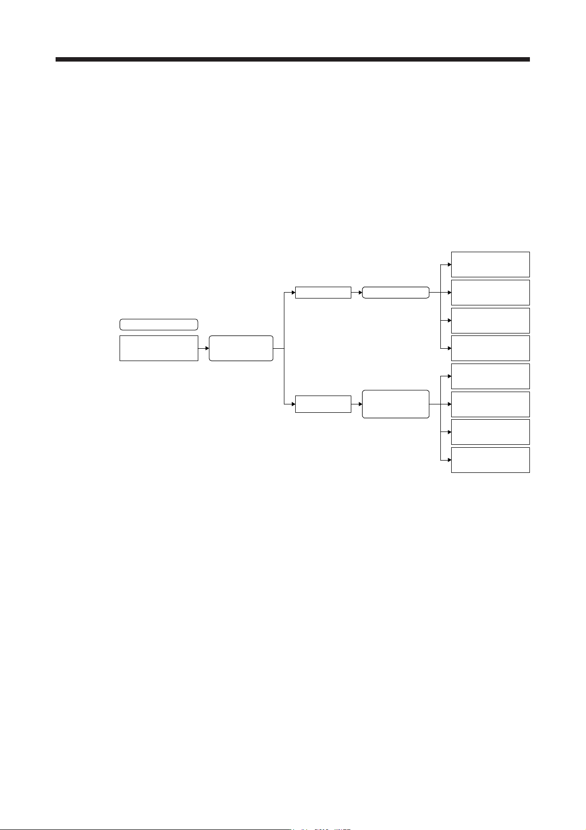
(1) Mode selection by the automatic identification of the servo amplifier
J4 mode/J3 compatibility mode is identified automatically depending on the connected controller.
When the controller makes a connection request with SSCNET III/H communication, the mode will be
"J4 mode". For SSCNET communication, it will be "J3 compatibility mode".
For the J3 compatibility mode, standard control, linear servo motor control, or direct drive motor control
will be identified automatically with a motor (encoder) connected to the servo amplifier. For the J4 mode,
the operation mode will be the setting of [Pr. PA01].
J4 mode/J3 compatibility
mode automatic
identification
Controller
connection check
J4 mode
J3 compatibility
mode
Connected encoder
check (automatic
identification)
Standard control
(rotary servo motor)
Direct drive motor
control
Factory setting
Linear servo motor
control
Fully closed
loop control
[Pr. PA01] setting
Standard control
(rotary servo motor)
Direct drive motor
control
Linear servo motor
control
Fully closed
loop control