sh030106u.pdf - 第559页
17. APPLICATIO N OF FUNCTIONS 17 - 8 17.1.7 Cauti ons for t he J3 c ompatib ility mode The J3 com patib ility mode ar e partly changed and has res trictio ns compar ed w ith MR-J 3 series. (1) The alarm disp lay was c ha…

17. APPLICATION OF FUNCTIONS
17 - 7
(3) Setting of MR Configurator2
To use in the J3 compatibility mode, make the system setting as follows.
Operation mode in J3 compatibility mode System setting
MR-J3-B standard control mode (rotary servo motor) Select MR-J3-_B.
MR-J3-B fully closed loop control mode Select MR-J3-_B fully closed.
MR-J3-B linear servo motor control mode Select MR-J3-_B linear.
MR-J3-B DD motor control mode Select MR-J3-_B DD motor.
Cautions for using MR Configurator2
Use MR Configurator2 with software version 1.12N or later. Older version than 1.12N cannot be used.
Information about existing models (MR-J3) cannot be updated with the parameter setting range update
function. Register a new model to use.
The alarm will be displayed by 3 digits.
The robust disturbance compensation cannot be used.
17.1.6 Cautions for switching J4 mode/J3 compatibility mode
The J3 compatibility mode of the operation mode is automatically identified by factory setting depending on a
connected encoder. If a proper encoder is not connected at the first connection, the system will not start
normally due to a mismatch with a set mode with the controller. (For the J4 mode, you can set the operation
mode with [Pr. PA01].) For example, if the controller is connected without connecting a linear encoder at
linear servo motor driving, the servo amplifier will be the standard control mode (rotary servo motor). The
system will not start because the controller is connected with the linear servo motor driving amplifier.
When the operation mode mismatches, the servo amplifier will display [AL. 3E.1 Operation mode error].
Restore the factory settings or configure the correct settings (J4 mode/J3 compatibility mode and operation
mode) using the application "MR-J4(W)-B mode selection" or "MR Mode Change" described in section
17.1.1.

17. APPLICATION OF FUNCTIONS
17 - 8
17.1.7 Cautions for the J3 compatibility mode
The J3 compatibility mode are partly changed and has restrictions compared with MR-J3 series.
(1) The alarm display was changed from 2 digits (_ _) to 3 digits (_ _. _). The alarm detail number (._) is
displayed in addition to the alarm No (_ _). The alarm No. (_ _) is not changed.
(2) When the power of the servo amplifier is cut or fiber-optic cable is disconnected, the same type
communication can be cut regardless of connection order. When you power on/off the servo amplifier
during operation, use the connect/disconnect function of the controller. Refer to the following manuals for
detail.
MELSEC iQ-R Motion Controller Programming Manual (Common) (R16MTCPU/R32MTCPU) (IB-
0300237) "5.3.1 Connect/disconnect function of SSCNET communication"
Motion controller Q series Programming Manual (COMMON) (Q173D(S)CPU/Q172D(S)CPU) (IB-
0300134) "4.11.1 Connect/disconnect function of SSCNET communication"
MELSEC iQ-R Simple Motion Module User's Manual (Application)
(RD77MS2/RD77MS4/RD77MS8/RD77MS16) (IB-0300247) "8.12 Connect/Disconnect Function of
SSCNET Communication"
MELSEC-Q QD77MS Simple Motion Module User's Manual (IB-0300185) "14.12 Connect/disconnect
function of SSCNET communication"
MELSEC-L LD77MH Simple Motion Module User's Manual (IB-0300172) "14.13 Connect/disconnect
function of SSCNET communication"
MELSEC-L LD77MS Simple Motion Module User's Manual (Positioning Control) (IB-0300211) "14.13
Connect/disconnect function of SSCNET communication"
(3) The J3 compatibility mode has a functional compatibility. However, the operation timing may differ.
Check the operation timing on customer side to use.
(4) The J3 compatibility mode is not compatible with high-response control set by [Pr. PA01 Operation
mode].
(5) For MR-J3 series, a linear encoder was connected to the CN2L connector. For J4 (J3 compatibility
mode), it is connected to the CN2 connector. Therefore, set the two-wire/four-wire type of the linear
encoder in the J3 compatibility mode with [Pr. PC26], not with [Pr. PC04].
(6) When you use a linear servo motor, select linear servo motor with [Pr. PA17] and [Pr. PA18].
17. APPLICATION OF FUNCTIONS
17 - 9
17.1.8 Change of specifications of "J3 compatibility mode" switching process
(1) Detailed explanation of "J3 compatibility mode" switching
(a) Operation when using a servo amplifier before change of specifications
For the controllers in which "Not required" is described to controller reset in table 17.1, the mode will
be switched to "J3 compatibility mode" for all axes at the first connection. However, it takes about 10
s per axis for completing the connection.
For the controllers in which "Reset required" is described in table 17.1, the operation at the first
connection is shown in table 17.2. The LED displays will be "Ab." for all axes at the first connection
to the controller as shown in table 17.2. After that, resetting controller will change the 1-axis to "b01".
The 2-axis and later will not change from "Ab.". After that, one axis will be connected per two times
of controller reset.
Table 17.1 Controller reset required/not required list (before change of specifications)
Controller Model
Controller reset required/not required
Single-axis
connection
Multi-axis connection
Motion controller
R_MTCPU Not required Not required
Q17_DSCPU Not required Not required
Q17_DCPU Not required Not required
Q17_HCPU Not required Not required
Q170MCPU Not required Not required
Simple motion module
Positioning module
RD77MS_ Not required Not required
QD77MS_ Not required Not required
LD77MS_ Not required Not required
QD75MH_ Not required Not required
QD74MH_ Reset required Reset required
LD77MH_ Not required Not required
FX3U-20SSC-H Not required Reset required
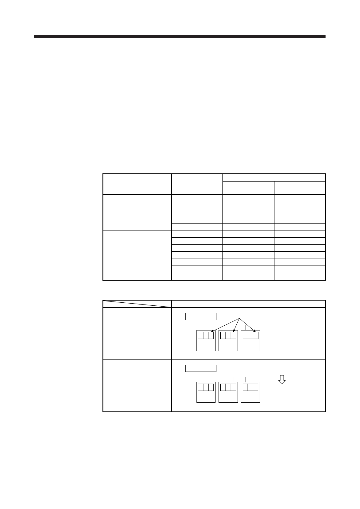
Table 17.2 Controller connection operation before change of specifications
Before change of specifications (software version A4 or earlier)
First connection of controller
Controller
Axis
No. 1
b.A
Axis
No. 2
b.A
Axis
No. 3
b.A
"Ab." is displayed and stops
After controller reset
Controller
Axis
No. 1
01b
Axis
No. 2
b.A
Axis
No. 3
b.A
"b01" is displayed on axis No. 1, "Ab." is
displayed on axis No. 2 and later.
One axis is connected
per reset.