sh030106u.pdf - 第564页
17. APPLICATIO N OF FUNCTIONS 17 - 13 The followi ng sho ws how to use th e J3 exte nsion fu nction. (1) Settings of J3 ext ensio n function POINT To set the J 3 extensio n fun ction, co nnect a p ersonal c omputer w ith…

17. APPLICATION OF FUNCTIONS
17 - 12
The following shows functions used with the J3 extension function.
Function Description
Detailed
explanation
Gain switching function
(Vibration suppression control
2 and model loop gain)
You can switch gains during rotation/stop, and can use input devices to switch gains
during operation.
Section
17.1.9 (6)
Advanced vibration
suppression control II
This function suppresses vibration at the arm end or residual vibration.
Section
17.1.9 (5) (c)
Machine resonance
suppression filter 3
Machine resonance
suppression filter 4
Machine resonance
suppression filter 5
This is a filter function (notch filter) which decreases the gain of the specific frequency
to suppress the resonance of the mechanical system.
Section
17.1.9 (5) (a)
Shaft resonance suppression
filter
When a load is mounted to the servo motor shaft, resonance by shaft torsion during
driving may generate a mechanical vibration at high frequency. The shaft resonance
suppression filter suppresses the vibration.
Section
17.1.9 (5) (b)
Robust filter
This function provides better disturbance response in case low response level that
load to motor inertia ratio is high for such as roll send axes.
[Pr. PX31]
One-touch tuning
Gain adjustment is performed just by one click on a certain button on MR
Configurator2.
MR Configurator2 is necessary for this function.
Section
17.1.9 (4)
Tough drive function
This function makes the equipment continue operating even under the condition that
an alarm occurs.
The tough drive function includes two types: the vibration tough drive and the
instantaneous power failure tough drive.
Section
17.1.9 (7)
SEMI-F47 function (Note)
Enables to avoid triggering [AL. 10 Undervoltage] using the electrical energy charged
in the capacitor in case that an instantaneous power failure occurs during operation.
Use a 3-phase for the input power supply of the servo amplifier. Using a 1-phase 200
V AC for the input power supply will not comply with SEMI-F47 standard.
[Pr. PX25]
[Pr. PX28]
Section
17.1.9 (8)
Drive recorder function
This function continuously monitors the servo status and records the status transition
before and after an alarm for a fixed period of time. You can check the recorded data
on the drive recorder window on MR Configurator2 by clicking the "Graph" button.
However, the drive recorder will not operate on the following conditions.
1. You are using the graph function of MR Configurator2.
2. You are using the machine analyzer function.
3. [Pr. PX30] is set to "-1".
4. The controller is not connected (except the test operation mode).
5. An alarm related to the controller is occurrin
g
.
[Pr. PX29]
Power monitoring function
This function calculates the power running energy and the regenerative power from
the data in the servo amplifier such as speed and current. Power consumption and
others are displayed on MR Configurator2 in the system of SSCNET III/H. Since the
servo amplifier sends data to a servo system controller, you can analyze the data and
display the data on a display.
Machine diagnosis function
From the data in the servo amplifier, this function estimates the friction and vibrational
component of the drive system in the equipment and recognizes an error in the
machine parts, including a ball screw and bearing.
MR Configurator2 is necessary for this function.
Lost motion compensation
function
This function improves the response delay occurred when the machine moving
direction is reversed. This is used with servo amplifiers with software version B4 or
later.
Section
17.1.9 (9)
Note. For servo s
y
stem controllers which are available with this, contact
y
our local sales office.
17. APPLICATION OF FUNCTIONS
17 - 13
The following shows how to use the J3 extension function.
(1) Settings of J3 extension function
POINT
To set the J3 extension function, connect a personal computer with MR
Configurator2 of software version 1.25B or later to the servo amplifier with USB
cable.
The extension control 2 parameters ([Pr. PX_ _ ]) cannot be set from a
controller.
To use the J3 the extension function, enable the setting of the extension control 2 parameters ([Pr. PX_
_ ]). Set as follows using MR Configurator2.
(a) Setting to enable the extension control 2 parameters ([Pr. PX_ _ ])
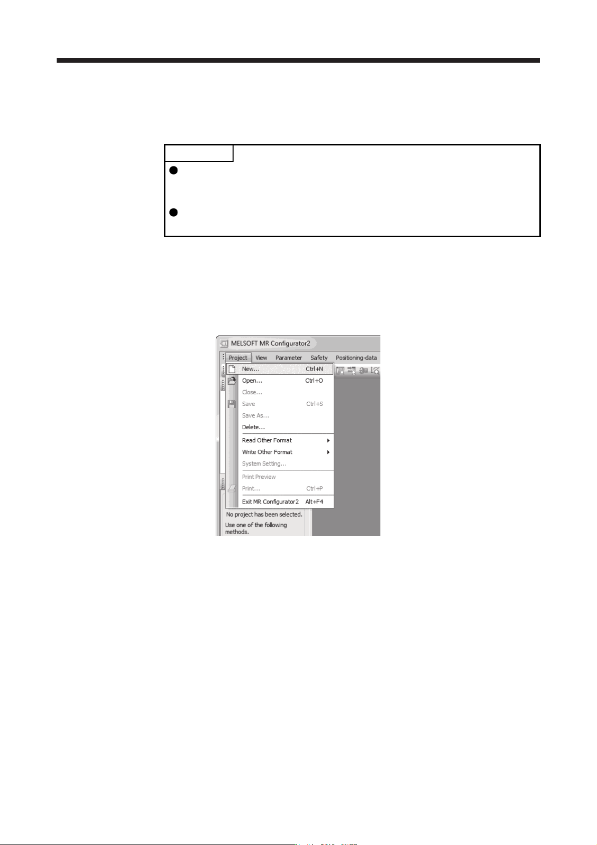
1) Open the "Project" menu and click "New" in MR Configurator2. The "New" window will be
displayed.
17. APPLICATION OF FUNCTIONS
17 - 14
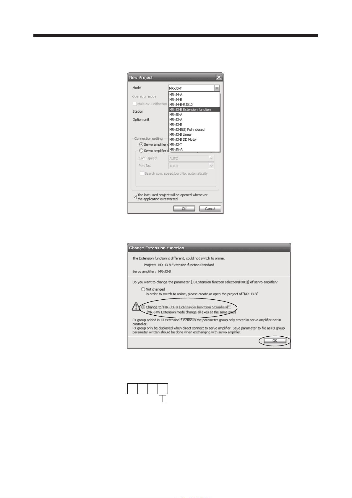
2) Select "MR-J3-B extension function" of model selection in the "New" window and click "OK". The
"Extension function change" window will be displayed.
3) Click "Change to MR-J3-B extension function" in the "Extension function change" window and
click "OK". Now, you can set the extension control 2 parameters ([Pr. PX_ _ ]).
(b) Setting to enable the J3 extension function
To enable the J3 extension function, set [Pr. PX01] to "_ _ _ 1".
000
[Pr. PX01]
J3 extension function selection
0: Disabled
1: Enabled