sh030106u.pdf - 第568页
17. APPLICATIO N OF FUNCTIONS 17 - 17 (3) Extension c ontrol 2 p arameters ([Pr. PX_ _ ]) d etailed list No. Sym bol Name and function Initial value [unit] Setting range PX01 **J3EX J3 extension function Select enabled o…
17. APPLICATION OF FUNCTIONS
17 - 16
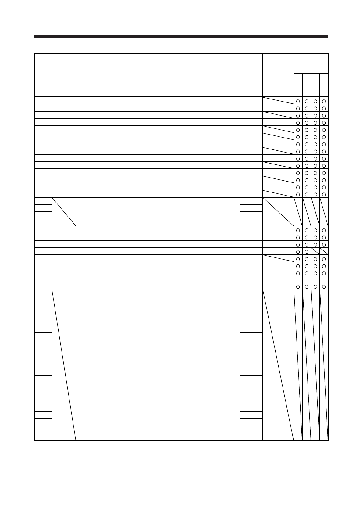
No. Symbol Name
Initial
value
Unit
J3
compatibility
mode
Standard
Full.
Lin.
DD
PX18 NHQ3 Notch shape selection 3 0000h
PX19 NH4 Machine resonance suppression filter 4 4500 [Hz]
PX20 NHQ4 Notch shape selection 4 0000h
PX21 NH5 Machine resonance suppression filter 5 4500 [Hz]
PX22 NHQ5 Notch shape selection 5 0000h
PX23 XOP3 Function selection X-3 0000h
PX24 FRIC Machine diagnosis function - Friction judgment speed 0 [r/min]/[mm/s]
PX25 *TDS Tough drive setting 0000h
PX26 OSCL1 Vibration tough drive - Oscillation detection level 50 [%]
PX27 *OSCL2 Vibration tough drive function selection 0000h
PX28 CVAT SEMI-F47 function - Instantaneous power failure detection time 200 [ms]
PX29 DRAT Drive recorder arbitrary alarm trigger setting 0000h
PX30 DRT Drive recorder switching time setting 0 [s]
PX31 XOP4 Function selection X-4 0000h
PX32 For manufacturer setting 0
PX33 0.0
PX34 0.0
PX35 50
PX36 LMCP Lost motion compensation positive-side compensation value selection 0 [0.01%]
PX37 LMCN Lost motion compensation negative-side compensation value selection 0 [0.01%]
PX38 LMFLT Lost motion filter setting 0 [0.1 ms]
PX39 TOF Torque offset 0 [0.01%]
PX40 *LMOP Lost motion compensation function selection 0000h
PX41 LMCD Lost motion compensation timing 0 [0.1 ms]
PX42 LMCT Lost motion compensation non-sensitive band 0
[pulse]/
[kpulse]
PX43 **STOD STO diagnosis error detection time 0 [s]
PX44 For manufacturer setting 0000h
PX45 0000h
PX46 0000h
PX47 0000h
PX48 0000h
PX49 0000h
PX50 0000h
PX51 0000h
PX52 0000h
PX53 0000h
PX54 0000h
PX55 0000h
PX56 0000h
PX57 0000h
PX58 0000h
PX59 0000h
PX60 0000h
PX61 0000h
PX62 0000h
PX63 0000h
PX64 0000h
17. APPLICATION OF FUNCTIONS
17 - 17
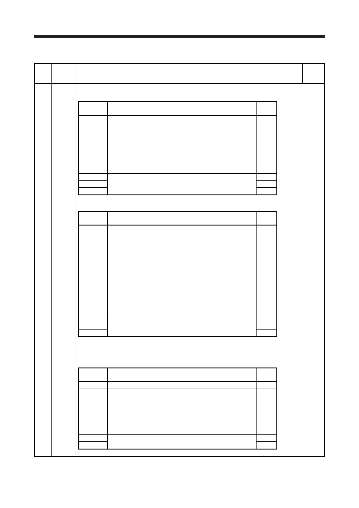
(3) Extension control 2 parameters ([Pr. PX_ _ ]) detailed list
No. Symbol Name and function
Initial
value
[unit]
Setting
range
PX01 **J3EX J3 extension function
Select enabled or disabled of the J3 extension function.
Refer to the
"Name and
function" column.
Setting
digit
Explanation
Initial
value
_ _ _ x J3 extension function selection
0: Disabled
1: Enabled
When you enable the J3 extension function selection, setting of [Pr.
PX01] to [Pr. PX35] will be enabled and you will be able to also use
functions in J4 mode with J3 compatibility mode. Additionally, the
J3 extension function of the amplifier differs from MR-J3-B in
motion.
0h
_ _ x _ For manufacturer setting 0h
_ x _ _ 0h
x _ _ _ 0h
PX02 XOP1 Function selection X-1
Refer to the
"Name and
function" column.
Setting
digit
Explanation
Initial
value
_ _ _ x Vibration suppression mode selection
0: Standard mode
1: 3 inertia mode
2: Low response mode
When two low resonance frequencies are generated, select "3
inertia mode (_ _ _ 1)". When the load to motor inertia ratio
exceeds the recommended load to motor inertia ratio, select "Low
response mode (_ _ _ 2)".
When you select the standard mode or low response mode,
"Vibration suppression control 2" is not available.
When you select the 3 inertia mode, the feed forward gain is not
available.
Before changing the control mode with the controller during the 3
inertia mode or low response mode, stop the motor.
0h
_ _ x _ For manufacturer setting 0h
_ x _ _ 0h
x _ _ _ 0h
PX03 VRFTX Vibration suppression control tuning mode (advanced vibration suppression control II)
This is used to set the vibration suppression control tuning. Refer to (5) (c) in this section for
details.
Refer to the
"Name and
function" column.
Setting
digit
Explanation
Initial
value
_ _ _ x For manufacturer setting 0h
_ _ x _ Vibration suppression control 2 tuning mode selection
Select the tuning mode of the vibration suppression control 2. To
enable the digit, select "3 inertia mode (_ _ _ 1)" of "Vibration
suppression mode selection" in [Pr. PX02 Function selection X-1].
0: Disabled
1: Automatic setting
2: Manual setting
0h
_ x _ _ For manufacturer setting 0h
x _ _ _ 0h

17. APPLICATION OF FUNCTIONS
17 - 18
No. Symbol Name and function
Initial
value
[unit]
Setting
range
PX04 VRF21
Vibration suppression control 2 - Vibration frequency
Set the vibration frequency for vibration suppression control 2 to suppress low-frequency
machine vibration.
To enable the setting value, set "Vibration suppression mode selection" to "3 inertia mode (_ _
_ 1)" in [Pr. PX02].
When "Vibration suppression control 2 tuning mode selection" is set to "Automatic setting (_ _
1 _)" in [Pr. PX03], this parameter will be set automatically. When "Manual setting (_ _ 2 _)" is
selected, the setting written to the parameter is used. The setting range of this parameter
varies, depending on the value in [Pr. PB07]. If a value out of the range is set, the vibration
suppression control will be disabled. Refer to section 17.1.9
(
5
)
(
c
)
for details.
100.0
[Hz]
0.1
to
300.0
PX05 VRF22 Vibration suppression control 2 - Resonance frequency
Set the resonance frequency for vibration suppression control 2 to suppress low-frequency
machine vibration.
To enable the setting value, set "Vibration suppression mode selection" to "3 inertia mode (_ _
_ 1)" in [Pr. PX02].
When "Vibration suppression control 2 tuning mode selection" is set to "Automatic setting (_ _
1 _)" in [Pr. PX03], this parameter will be set automatically. When "Manual setting (_ _ 2 _)" is
selected, the setting written to the parameter is used. The setting range of this parameter
varies, depending on the value in [Pr. PB07]. If a value out of the range is set, the vibration
suppression control will be disabled. Refer to section 17.1.9 (5) (c) for details.
100.0
[Hz]
0.1
to
300.0
PX06 VRF23 Vibration suppression control 2 - Vibration frequency damping
Set a damping of the vibration frequency for vibration suppression control 2 to suppress low-
frequency machine vibration.
To enable the setting value, set "Vibration suppression mode selection" to "3 inertia mode (_ _
_ 1)" in [Pr. PX02].
When "Vibration suppression control 2 tuning mode selection" is set to "Automatic setting (_ _
1 _)" in [Pr. PX03], this parameter will be set automatically. When "Manual setting (_ _ 2 _)" is
selected, the setting written to the parameter is used. Refer to section 17.1.9 (5) (2) for details.
0.00
0.00
to
0.30
PX07 VRF24 Vibration suppression control 2 - Resonance frequency damping
Set a damping of the resonance frequency for vibration suppression control 2 to suppress low-
frequency machine vibration.
To enable the setting value, set "Vibration suppression mode selection" to "3 inertia mode (_ _
_ 1)" in [Pr. PX02].
When "Vibration suppression control 2 tuning mode selection" is set to "Automatic setting (_ _
1 _)" in [Pr. PX03], this parameter will be set automatically. When "Manual setting (_ _ 2 _)" is
selected, the setting written to the parameter is used. Refer to section 17.1.9 (5) (2) for details.
0.00
0.00
to
0.30
PX08 VRF21B Vibration suppression control 2 - Vibration frequency after gain switching
Set the vibration frequency for vibration suppression control 2 when the gain switching is
enabled.
When you set a value less than 0.1 Hz, the value will be the same as [Pr. PX04].
To enable this, select "3 inertia mode (_ _ _ 1)" of "Vibration suppression mode selection" in
[Pr. PX02].
This parameter will be enabled only when the following conditions are fulfilled.
"Gain adjustment mode selection" in [Pr. PA08] is "Manual mode (_ _ _ 3)".
"Vibration suppression control 2 tuning mode selection" in [Pr. PX03] is "Manual setting (_ _
2 _)".
"Gain switching selection" in [Pr. PB26] is "Control command from controller is enabled (_ _
_ 1)".
When you set "0.0", the value will be the same as [Pr. PX04].
Switching during driving may cause a shock. Be sure to switch them after the servo motor or
linear servo motor stops.
0.0
[Hz]
0.0
to
300.0