sh030106u.pdf - 第590页
17. APPLICATIO N OF FUNCTIONS 17 - 39 (c) Caution for on e-touch tuning 1) Caution c omm on for us er comm and met hod and am pli fier com mand met hod a) The tunin g is not availab le i n the torqu e contr ol mod e. b) …
17. APPLICATION OF FUNCTIONS
17 - 38
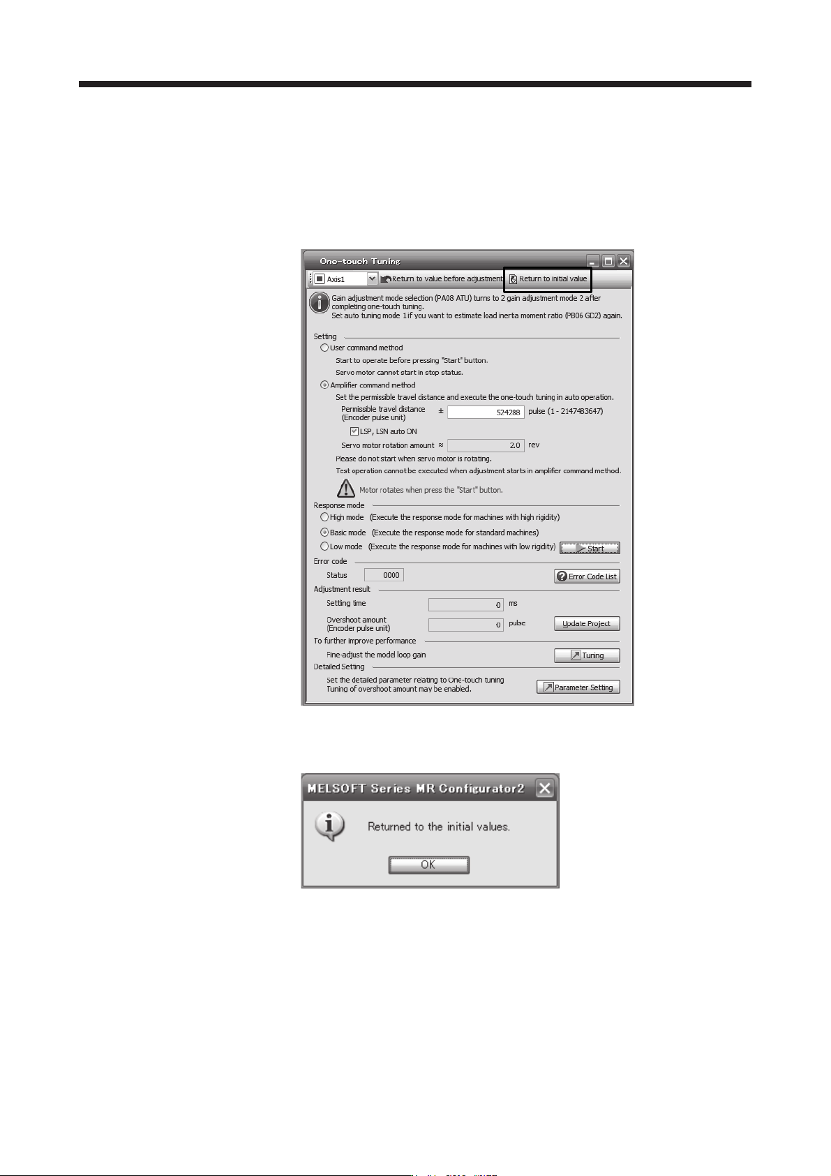
8) Initializing one-touch tuning
Clicking "Return to initial value" in the one-touch tuning window of MR Configurator2 enables to
return the parameter to the initial value. Refer to table 17.5 for the parameters which you can
initialize.
Clicking "Return to value before adjustment" in the one-touch tuning window of MR Configurator2
enables to return the parameter to the value before clicking "start".
When the initialization of one-touch tuning is completed, the following window will be displayed.
(returning to initial value)

17. APPLICATION OF FUNCTIONS
17 - 39
(c) Caution for one-touch tuning
1) Caution common for user command method and amplifier command method
a) The tuning is not available in the torque control mode.
b) The one-touch tuning cannot be executed while an alarm or warning which does not continue
the motor driving is occurring.
c) The one-touch tuning cannot be executed during the following test operation mode.
Output signal (DO) forced output
Motor-less operation
d) If one-touch tuning is performed when the gain switching function is enabled, vibration and/or
unusual noise may occur during the tuning.
2) Caution for amplifier command method
a) Starting one-touch tuning while the servo motor is rotating displays "C006" at status in error
code, and the one-touch tuning cannot be executed.
b) One-touch tuning is not available during the test operation mode. The following test operation
modes cannot be executed during one-touch tuning.
Positioning operation
JOG operation
Program operation
Machine analyzer operation
c) After one-touch tuning is executed, control will not be performed by commands from the servo
system controller. To return to the state in which control is performed from the servo system
controller, reset the controller or cycle the power of the servo amplifier.
d) During one-touch tuning, the permissible travel distance may be exceeded due to overshoot,
set a value sufficient to prevent machine collision.
e) When Auto tuning mode 2, Manual mode, or 2 gain adjustment mode 2 is selected in [Pr.
PA08 Auto tuning mode], the load to motor inertia ratio will not be estimated. An optimum
acceleration/deceleration command will be generated by [Pr. PB06 Load to motor inertia
ratio/load to motor mass ratio] at the start of one-touch tuning. When the load to motor inertia
ratio is incorrect, the optimum acceleration/deceleration command may not be generated,
causing the tuning to fail.
f) When one-touch tuning is started by using USB communication, if the USB communication is
interrupted during the tuning, the servo motor will stop, and the tuning will also stop. The
parameter will return to the one at the start of the one-touch tuning.
g) When one-touch tuning is started via the controller, if communication between the controller
and the servo amplifier or personal computer is shut-off during the tuning, the servo motor will
stop, and the tuning will also stop. The parameter will return to the one at the start of the one-
touch tuning.
h) When one-touch tuning is started during the speed control mode, the mode will be switched to
the position control mode automatically. The tuning result may differ from the one obtained by
executing tuning by using the speed command.
17. APPLICATION OF FUNCTIONS
17 - 40
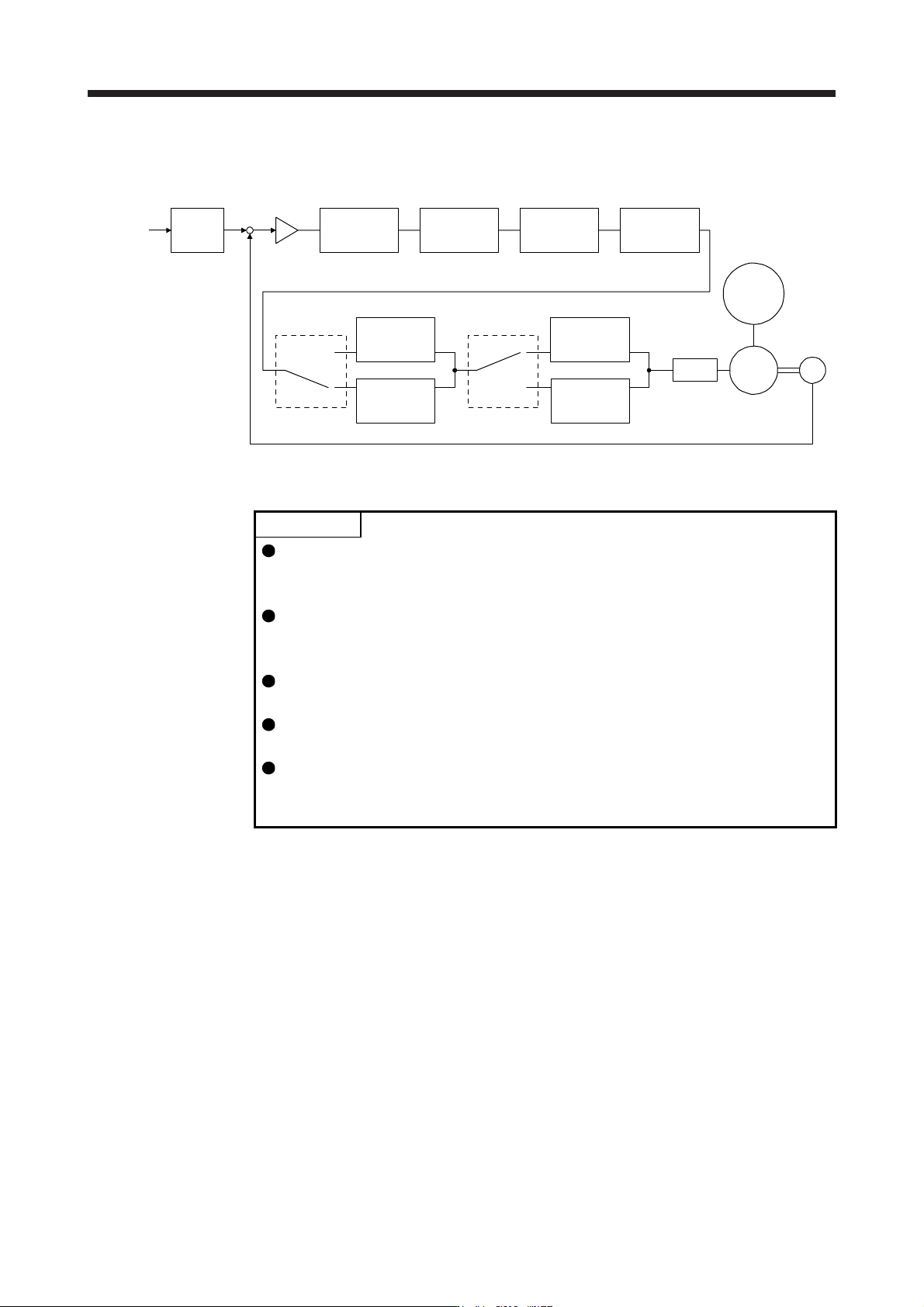
(5) Filter setting
The following filters are available with the J3 extension function.
Command
pulse train
Command
filter
Low-pass
filter
setting
Encoder
Servo motor
PWM
M
Load
[Pr. PB18]
+
-
Machine
resonance
suppression
filter 1
[Pr. PB13] [Pr. PB15]
Machine
resonance
suppression
filter 2
Machine
resonance
suppression
filter 3
Machine
resonance
suppression
filter 4
Machine
resonance
suppression
filter 5
Shaft
resonance
suppression
filter
Robust filter
[Pr. PB17]
Speed
control
[Pr. PX17]
[Pr. PX19] [Pr. PX21]
[Pr. PX20] [Pr. PX31]
(a) Machine resonance suppression filter
POINT
The machine resonance suppression filter is a delay factor for the servo system.
Therefore, vibration may increase if you set an incorrect resonance frequency or
set notch characteristics too deep or too wide.
If the frequency of machine resonance is unknown, decrease the notch
frequency from higher to lower ones in order. The optimum notch frequency is
set at the point where vibration is minimal.
A deeper notch has a higher effect on machine resonance suppression but
increases a phase delay and may increase vibration.
A wider notch has a higher effect on machine resonance suppression but
increases a phase delay and may increase vibration.
The machine characteristic can be grasped beforehand by the machine analyzer
on MR Configurator2. This allows the required notch frequency and notch
characteristics to be determined.
If a mechanical system has a unique resonance point, increasing the servo system response level
may cause resonance (vibration or unusual noise) in the mechanical system at that resonance
frequency. Using the machine resonance suppression filter and adaptive tuning can suppress the
resonance of the mechanical system. The setting range is 10 Hz to 4500 Hz.