sh030106u.pdf - 第622页
17. APPLICATIO N OF FUNCTIONS 17 - 71 (4) Rotation direction setting Rotation dir ections can be diff erent amo ng a c ontroll er comma nd , maste r axis, and sl ave axe s. To align the directions , set [Pr. PA1 4] r efe…
17. APPLICATION OF FUNCTIONS
17 - 70
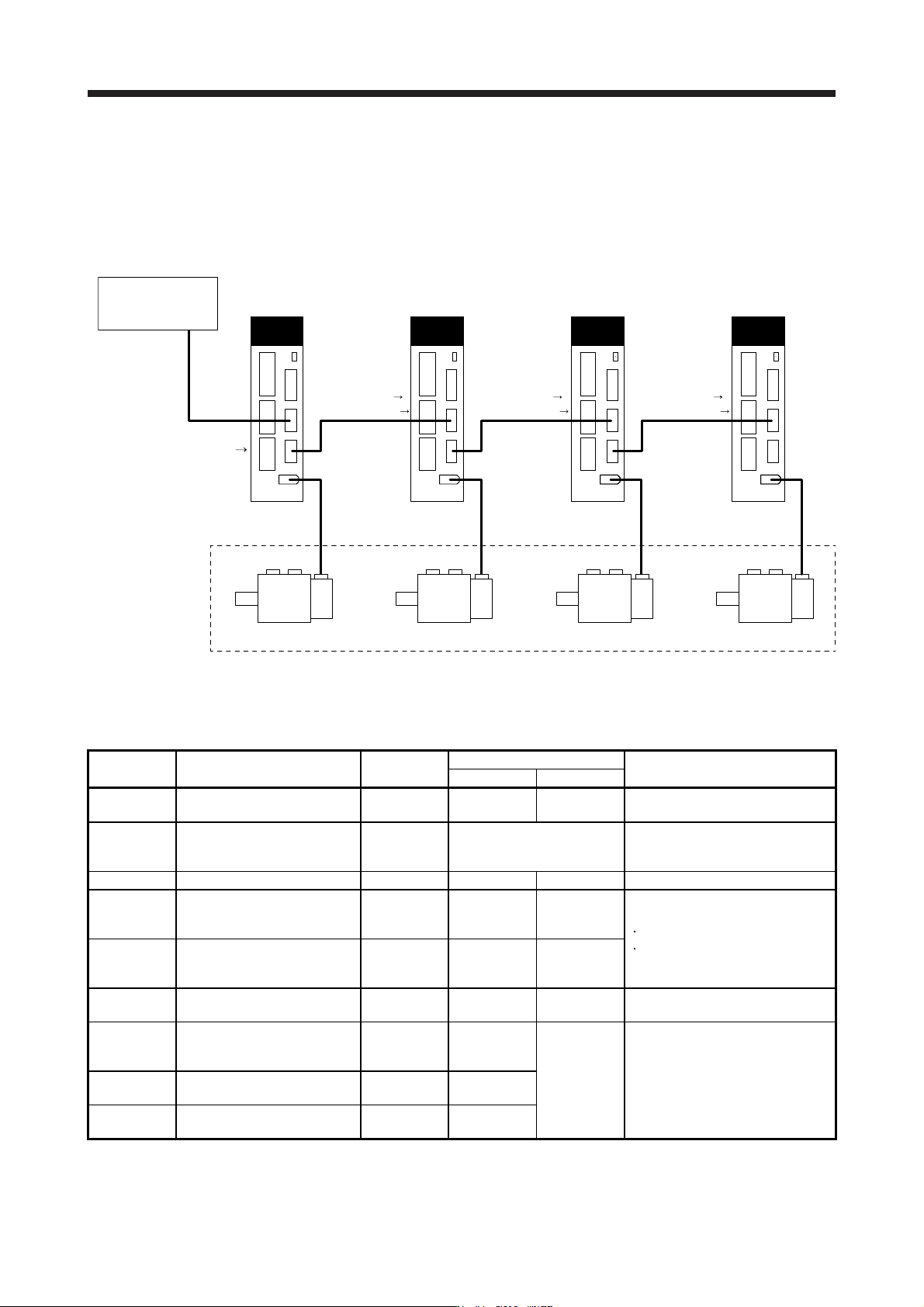
Eight master axes can be set at most per one system of SSCNET III/H. The maximum number of slave
axes to each master axis is not limited. However, the total number of the master and slave axes should
be the maximum number of the servo amplifiers at most. In addition, when an SSCNET III/H
communication shut-off occurs due to malfunction of a servo amplifier, the malfunctioning axis and later
axis cannot be communicated. Therefore, the first amplifier from the controller via SSCNET III/H cable
should be master axis.
Master axis
MR-J4-_B_(-RJ)
CN2 CN2 CN2 CN2
Slave axis 1
MR-J4-_B_(-RJ)
Slave axis 2
MR-J4-_B_(-RJ)
Slave axis 3
MR-J4-_B_(-RJ)
These are for the
same machine.
Controller
Position
command
[Driver communication]
Torque command
Speed limit command
[Driver communication] [Driver communication]
Torque command
Speed limit command
Torque command
Speed limit command
(3) Parameter setting for the master-slave operation function
To use the master-slave operation function, the following parameter settings are necessary. For details
of the parameters, refer to section 5.2.1 and 5.2.4.
No. Name Initial value
Setting value
Setting
Master axis Slave axis
PA04
Forced stop deceleration
function selection
2000 0 _ _ _ 0 _ _ _
Used to disable the forced stop
deceleration function.
PA14
Rotation direction
selection/travel direction
selection
0 Refer to section 5.2.1.
Used to set a torque generation
direction.
PD15 (Note) Driver communication setting 0000 0001 0010 Master and slave setting
PD16 (Note)
Driver communication setting -
Master - Transmit data
selection 1
0000 0038 0000
Communication data from master to
slave
Torque command
Speed limit value
PD17 (Note)
Driver communication setting -
Master - Transmit data
selection 2
0000 003A 0000
PD20 (Note)
Master axis No. selection 1 for
slave
0 0
Master axis
No.
Master axis No. of transmitting data
PD30
Master-slave operation -
Torque command coefficient on
slave
0 0
Refer to
section 5.2.4.
Ratio of torque command of slave
axis, ratio of speed limit value, and
setting of speed limit minimum value
PD31
Master-slave operation - Speed
limit coefficient on slave
0 0
PD32
Master-slave operation - Speed
limit adjusted value on slave
0 0
Note.
A
lwa
y
s set this with parameters of the controller.
17. APPLICATION OF FUNCTIONS
17 - 71
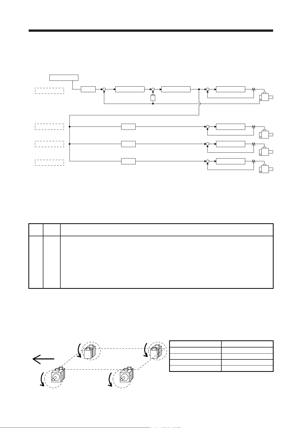
(4) Rotation direction setting
Rotation directions can be different among a controller command, master axis, and slave axes. To align
the directions, set [Pr. PA14] referring to (4) in this section. Not doing so can cause such as an overload
due to a reverse direction torque against machine system rotation direction.
Controller
Master axis
Slave axis 1
Slave axis 2
Slave axis 3
Position control Speed control
S
Current control
+
--
Current control
Current control
Current control
[Pr. PA14]
0 or 1 (Note)
[Pr. PA14]
0 or 1 (Note)
[Pr. PA14]
0 or 1 (Note)
[Pr. PA14]
0 or 1 (Note)
+
-
+
-
+
-
+
-
+
POL
POL
POL
POL
Note. Settin
g
"1" will reverse the polarit
y
.
Fig. 17.3 Rotation direction setting of master and slave axes with torque command method for an
example of one master axis and three slave axes
Table 17.11 Rotation direction setting parameter
No. Symbol Name and function
PA14 *POL
Rotation direction selection
1. For master axis
Select a servo motor rotation direction of master axis to SSCNET controller command.
0: Servo motor CCW rotation in positioning address increase direction
1: Servo motor CW rotation in positioning address increase direction
2. For slave axis
Select servo motor rotation direction to a command from master axis.
0: Torque command polarity from master axis
1: Reverse of torque command polarity from master axis
The following shows a setting example of rotation direction for a platform truck with one master axis and
three slave axes.
To set a rotation direction of the servo motor according to the moving direction, set the torque command
polarity to the slave axis 1 the same as that to the master axis, and set the opposite polarity to the slave
axis 2 and slave axis 3 from the master axis.
Slave axis 2
Slave axis 1Master axis
Slave axis 3
Moving direction
CW
CCW CCW
CW
[Pr. PA14] setting
Axis [Pr. PA14]
Master axis 0
Slave axis 1 0
Slave axis 2 1
Slave axis 3 1
17. APPLICATION OF FUNCTIONS
17 - 72
17.3 Scale measurement function
The scale measurement function transmits position information of a scale measurement encoder to the
controller by connecting the scale measurement encoder in semi closed loop control.
POINT
The scale measurement function is available for the servo amplifiers of software
version A8 or later.
When a linear encoder is used as a scale measurement encoder for this servo
amplifier, "Linear Encoder Instruction Manual" is necessary.
When the scale measurement function is used for MR-J4-_B_ servo amplifiers,
the following restrictions apply. However, these restrictions will not be applied for
MR-J4-_B_-RJ servo amplifiers.
A/B/Z-phase differential output type encoder cannot be used.
The scale measurement encoder and servo motor encoder are compatible
with only the two-wire type. The four-wire type scale measurement encoder
and servo motor encoder cannot be used.
When you use the HG-KR and HG-MR series for driving and scale
measurement encoder, the optional four-wire type encoder cables (MR-
EKCBL30M-L, MR-EKCBL30M-H, MR-EKCBL40M-H, and MR-EKCBL50M-H)
cannot be used. When an encoder cable of 30 m to 50 m is needed, fabricate
a two-wire type encoder cable according to app. 8.
The scale measurement function compatible servo amplifier can be used with
any of the following controllers.
Motion controller R_MTCPU/Q17_DSCPU
Simple motion module RD77MS/QD77MS_/LD77MS_
For settings and restrictions of controllers compatible with the scale
measurement function, refer to user's manuals for each controller.
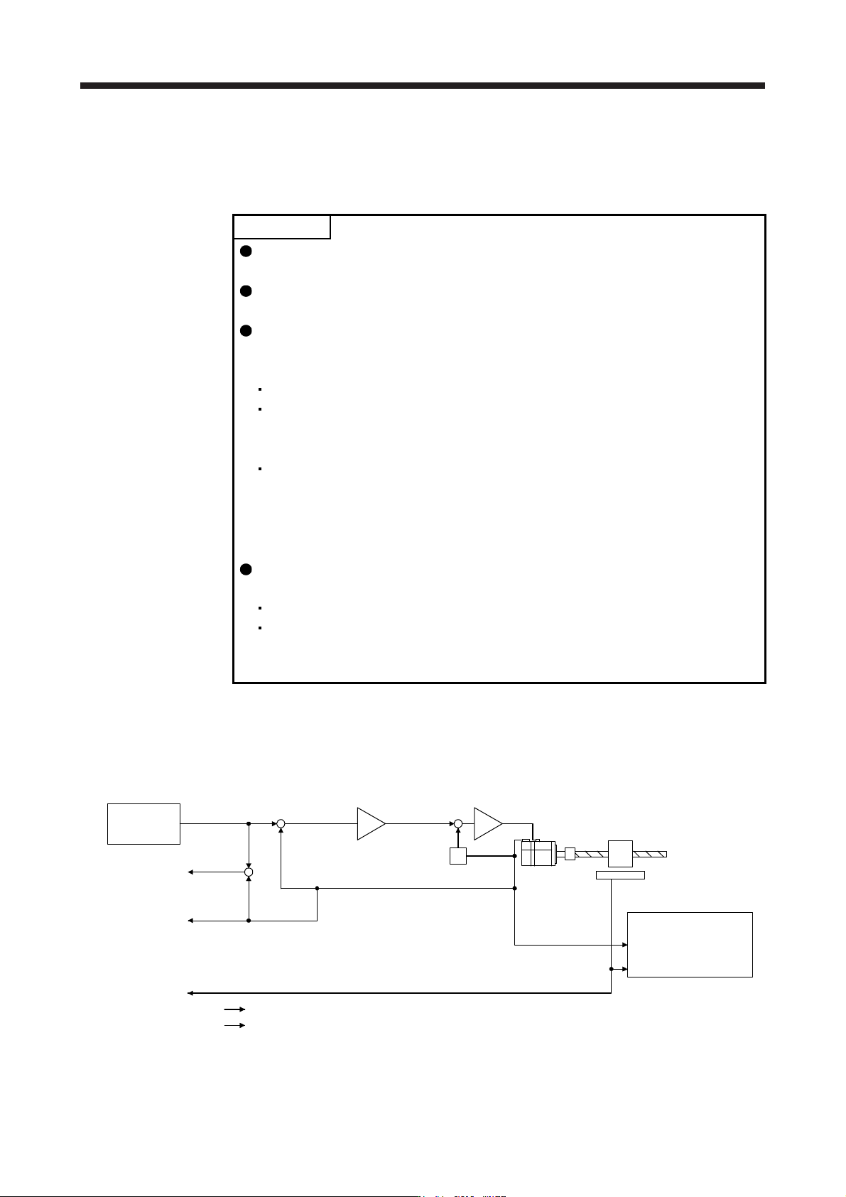
17.3.1 Functions and configuration
(1) Function block diagram
The following shows a block diagram of the scale measurement function. The control will be performed
per servo motor encoder unit for the scale measurement function.
Servo motor feedback pulses
(Servo motor resolution unit)
(Servo motor)
Droop pulses
(Servo motor)
Cumulative
feedback pulses
Cumulative
load-side
feedback pulses
Servo motor
Scale measurement encoder
Controller
S
Encoder pulse setting
([Pr. PA15], [Pr. PA16]
and [Pr. PC03])
+
-
+
-
+
-
Control
Monitor
Load-side feedback pulses
(Scale resolution unit)