sh030106u.pdf - 第653页
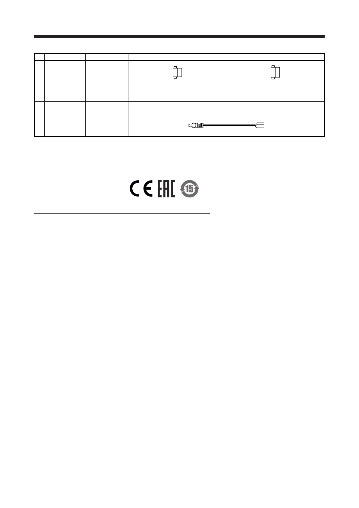
APPENDIX App. - 22 No. Produc t Model Description 1) Connector MR-J3-D05 attachment connector Connec tor for CN9: 1-1871940-4 (TE Connectiv ity) Connector for CN10: 1-1871940-8 (TE Connectivi ty) 2) STO cable MR-D05UDL3M…
APPENDIX
App. - 21
App. 5.13 Installation
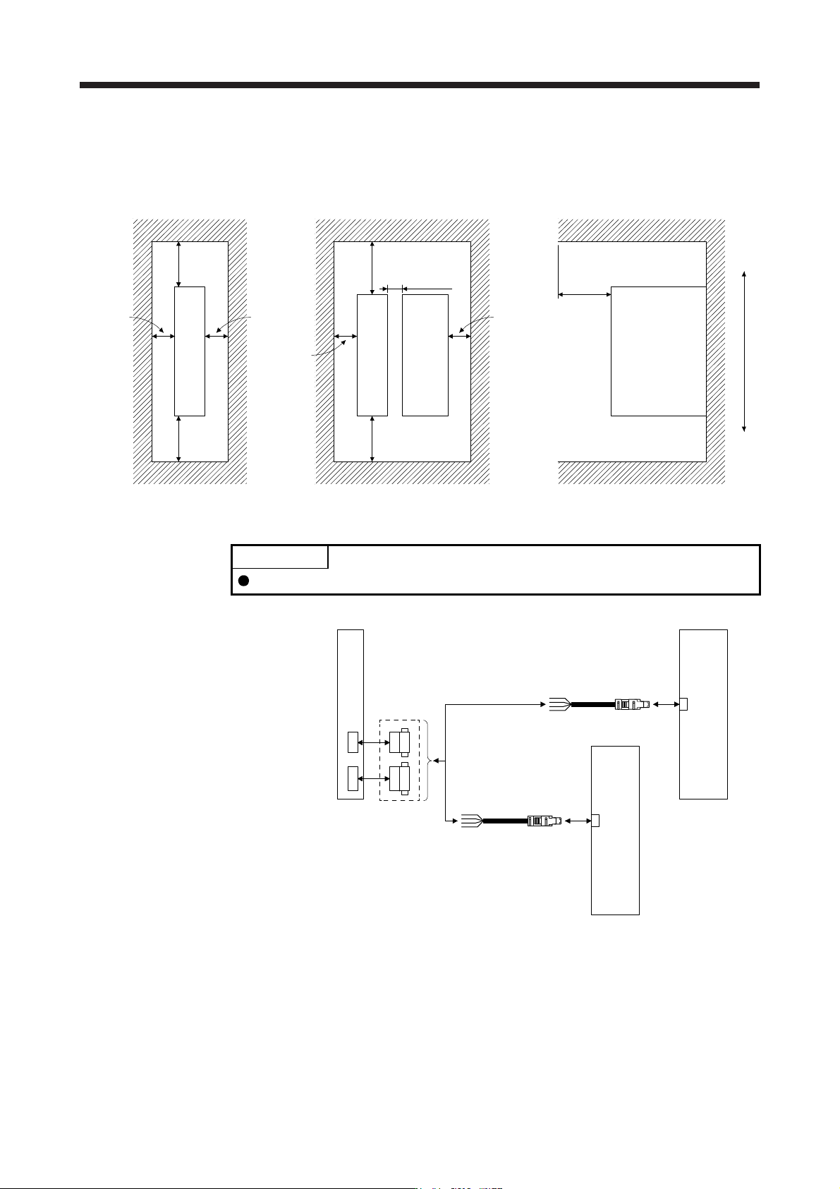
Follow the instructions in this section and install MR-J3-D05 in the specified direction. Leave clearances
between MR-J3-D05 and other equipment including the cabinet.
Cabine
t
10 mm or
longer
80 mm or longer
for wiring
30 mm or
longer
10 mm or
longer
Top
Bottom
40 mm or
longer
40 mm or
longer
40 mm or
longer
30 mm or
longer
100 mm or longer
10 mm or
longer
Cabine
t
Cabine
t
MR-J3-D05
MR-J3-D05
MR-J3-D05
Other device
App. 5.14 Combinations of cable/connector
POINT
MR-D05UDL_M (STO cable) for MR-J3 series cannot be used.
MR-J3-D05
attachment
connector
CN9
CN10
MR-J3-D05
2)
2)
CN8
MR-J4_B_(-RJ)
MR-J4_B_(-RJ)
1)
CN8
APPENDIX
App. - 22
No. Product Model Description
1) Connector
MR-J3-D05
attachment
connector
Connector for CN9: 1-1871940-4
(TE Connectivity)
Connector for CN10: 1-1871940-8
(TE Connectivity)
2) STO cable MR-D05UDL3M-B
Cable length: 3 m
Connector set: 2069250-1
(TE Connectivity)
App. 5.15. Compliance with standards
MR-J3-D05 complies with the following standard.
IEC/EN/KN 61800-3/GB 12668.3
COMPLIANCE WITH THE MACHINERY DIRECTIVES
The MR-J3-D05 complies with the safety components laid down in the Machinery directive (2006/42/EC).
APPENDIX
App. - 23
App. 6 How to adjust the error excessive alarm level
The error excessive alarm level can be adjusted as required.
(1) Parameters
The error excessive alarm level can be increased with the following parameters.
Parameter Symbol Name Setting range Unit
PC01 ERZ Error excessive alarm level 0 to 1000 [rev or mm]
PC06
"x _ _ _"
*COP3
Error excessive alarm/error excessive warning level unit
selection
0: 1 rev or 1 mm
1: 0.1 rev or 0.1 mm
2: 0.01 rev or 0.01 mm
3: 0.001 rev or 0.001 mm
0 to 3 -
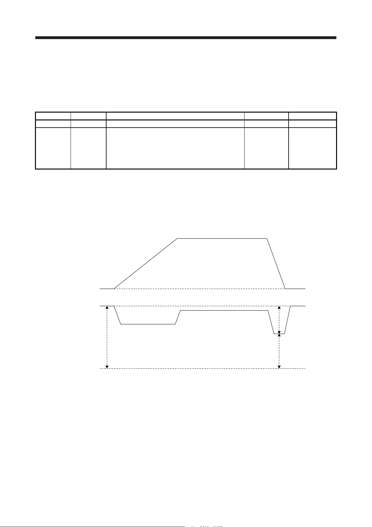
(2) Checking the error excessive alarm margin
Monitor the error excessive alarm margin using the graph function of MR Configurator2. When the
command position and feedback position match, the error excessive alarm margin is the maximum
pulse. Additionally, if the error excessive alarm margin is 0 pulses, [AL. 52 Error excessive alarm] will
occur. Calculate the pulse difference from the maximum and minimum pulses of "error excessive alarm
margin".
0 r/min
0 pulse
Error excessive
alarm margin
Servo motor speed
Differential pulse
Minimum pulse
Maximum pulse
(3) Adjusting the error excessive alarm level
Adjust the error excessive alarm level with [Pr. PC01] and " x _ _ _ " of [Pr. PC06] so that the following
formula is satisfied.
[Pr. PC01] × Unit set with "x _ _ _" of [Pr. PC06] > Error excessive alarm margin difference/Resolution
per revolution
For linear servo motors, the following value indicates the resolution per revolution.
[Pr. PL02 Linear encoder resolution setting - Numerator]/[Pr. PL03 Linear encoder resolution setting -
Denominator] × 1000