sh030106u.pdf - 第655页
APPENDIX App. - 24 App. 7 How to repl ace servo a mplifier wi thout magneti c pole det ection CAUTION Be sure to write t he mag netic po le infor mation of the s ervo amp lif ier befor e the replacemen t to the serv o am…
APPENDIX
App. - 23
App. 6 How to adjust the error excessive alarm level
The error excessive alarm level can be adjusted as required.
(1) Parameters
The error excessive alarm level can be increased with the following parameters.
Parameter Symbol Name Setting range Unit
PC01 ERZ Error excessive alarm level 0 to 1000 [rev or mm]
PC06
"x _ _ _"
*COP3
Error excessive alarm/error excessive warning level unit
selection
0: 1 rev or 1 mm
1: 0.1 rev or 0.1 mm
2: 0.01 rev or 0.01 mm
3: 0.001 rev or 0.001 mm
0 to 3 -
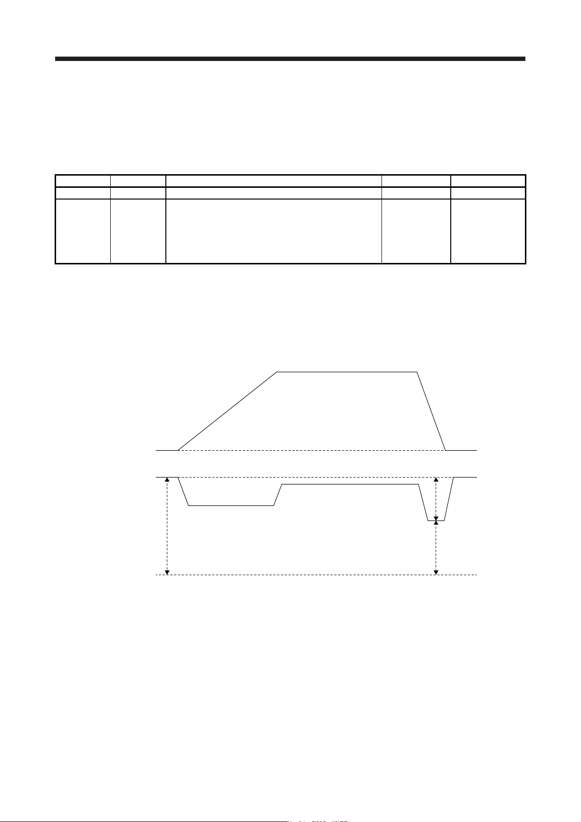
(2) Checking the error excessive alarm margin
Monitor the error excessive alarm margin using the graph function of MR Configurator2. When the
command position and feedback position match, the error excessive alarm margin is the maximum
pulse. Additionally, if the error excessive alarm margin is 0 pulses, [AL. 52 Error excessive alarm] will
occur. Calculate the pulse difference from the maximum and minimum pulses of "error excessive alarm
margin".
0 r/min
0 pulse
Error excessive
alarm margin
Servo motor speed
Differential pulse
Minimum pulse
Maximum pulse
(3) Adjusting the error excessive alarm level
Adjust the error excessive alarm level with [Pr. PC01] and " x _ _ _ " of [Pr. PC06] so that the following
formula is satisfied.
[Pr. PC01] × Unit set with "x _ _ _" of [Pr. PC06] > Error excessive alarm margin difference/Resolution
per revolution
For linear servo motors, the following value indicates the resolution per revolution.
[Pr. PL02 Linear encoder resolution setting - Numerator]/[Pr. PL03 Linear encoder resolution setting -
Denominator] × 1000
APPENDIX
App. - 24
App. 7 How to replace servo amplifier without magnetic pole detection
CAUTION
Be sure to write the magnetic pole information of the servo amplifier before the
replacement to the servo amplifier after the replacement. If the information before
and after replacement are different, the servo motor may operate unexpectedly.
When replacing the servo amplifier, carry out the magnetic pole detection again. If the magnetic pole
detection cannot be performed unavoidably, write the magnetic pole information from the servo amplifier
before the replacement to the one after the replacement using MR Configurator2.
(1) Procedures
(a) Read the magnetic pole information of the servo amplifier before the replacement.
(b) Write the read magnetic pole information to the servo amplifier after the replacement.
(c) Perform the test operation with the torque limit for ensuring the safety, and confirm that there is no
trouble.
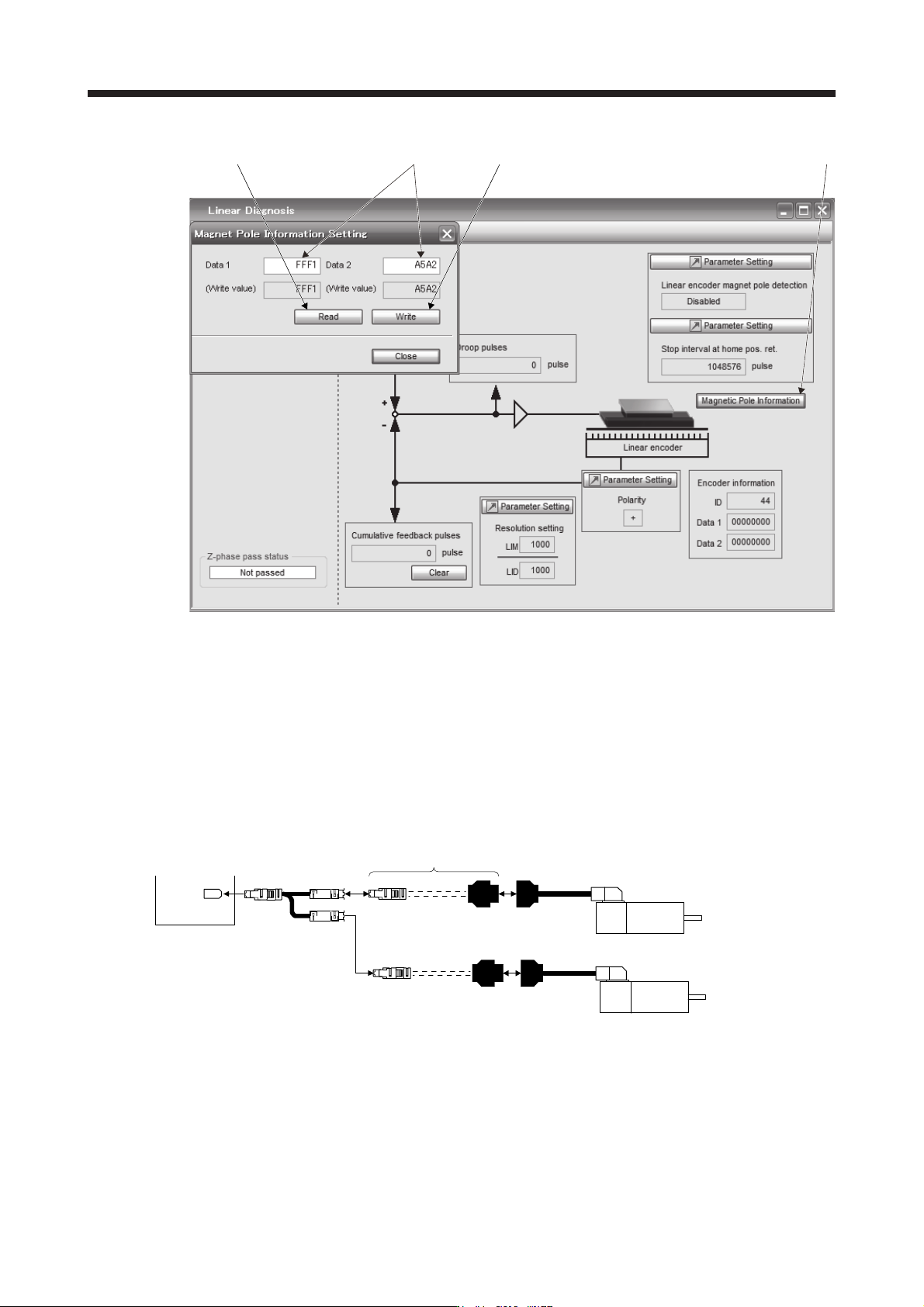
(2) Migration method of the magnetic pole information
(a) How to read the magnetic pole information from the servo amplifier before the replacement
1) Open the project in MR Configurator2, select "MR-J4-B" for model, and select "Linear" for
operation mode.
2) Check that the personal computer is connected with the servo amplifier, and select "Diagnosis"
and then "Linear diagnosis".
3) Click "Magnetic pole information" ( 1) in figure) to open the magnetic pole information window.
4) Click "Read All" of the magnetic pole information window. ( 2) in figure)
5) Confirm the data 1 and data 2 ( 3) in figure) of the magnetic pole information window and take
notes.
(b) How to write the magnetic pole information to the servo amplifier after the replacement
1) Open the project in MR Configurator2, select "MR-J4-B" for model, and select "Linear" for
operation mode.
2) Check that the personal computer is connected with the servo amplifier, and select "Diagnosis"
and then "Linear diagnosis".
3) Click "Magnetic pole information" ( 1) in figure) to open the magnetic pole information window.
4) Input the value of the magnetic pole information taken notes to the data 1 and data 2 ( 3) in
figure) of the magnetic pole information window.
5) Click "Write All" ( 4) in figure) of the magnetic pole information window.
6) Cycle the power of the servo amplifier.
APPENDIX
App. - 25
2) 3) 4) 1)
App. 8 Two-wire type encoder cable for HG-MR/HG-KR
Use a two-wire type encoder cable for the fully closed loop control by the MR-J4-_B_ servo amplifiers.
For MR-EKCBL_M-_ encoder cables for HG-MR and HG-KR, up to 20 m cables are two-wire type. If a two-
wire type encoder cable with a length of 20 m or more is required, fabricate it using the MR-ECNM connector
set as shown in the internal wiring diagram of this section. In this case, the cable should not be longer than
50 m.
App. 8.1 Configuration diagram
Servo amplifier
CN2
Fabricate a two-wire type
encoder cable.
CN2 MOTOR
SCALE
Servo motor
HG-KR
HG-MR
Servo motor
HG-KR
HG-MR
For driving
For load-side encode
r