sh030106u.pdf - 第658页
APPENDIX App. - 27 App. 9 SSC NET III cabl e (SC-J3BUS_M -C) manuf actured by Mitsubi s hi Electric System & Service POINT For the details of th e SSCNET III c ables, c ontact yo ur local sa les o ffice. Do not look …
APPENDIX
App. - 26
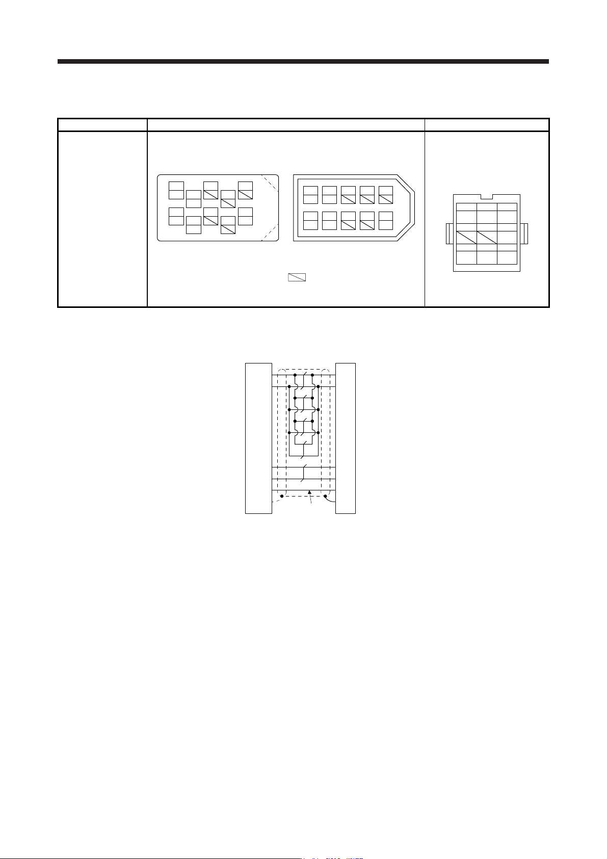
App. 8.2 Connector set
Connector set 1) Servo amplifier-side connector 2) Servo motor-side connector
MR-ECNM Receptacle: 36210-0100PL
Shell kit: 36310-3200-008
(3M)
Connector set: 54599-1019
(Molex)
Housing: 1-172161-9
Connector pin: 170359-1
(TE Connectivity or equivalent)
Cable clamp: MTI-0002
(Toa Electric Industrial)
MR
123
MRR BAT
456
P5
789
LG SHD
View seen from wiring side.
CONT
MRR
LG
P5
MR
BAT
4
2
8
6
15
10
37
9
View seen from wiring side. (Note)
or
P5 MR
BAT
MRR
LG
13 79
428610
5
V
iew seen from wiring side. (Note
)
Note. Keep open the pins shown with . Especially, pin 10 is provided
for manufacturer adjustment. If it is connected with any other pin, the
servo amplifier cannot operate normall
y
.
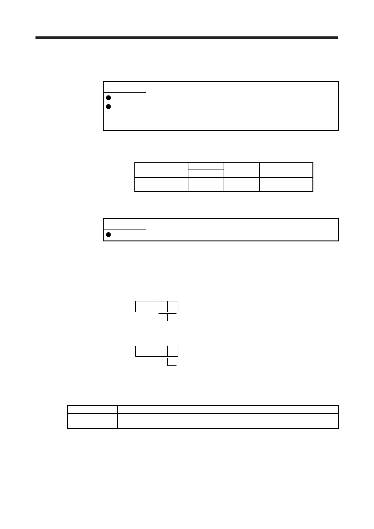
App. 8.3 Internal wiring diagram
(Note)
P5
LG
1
2
MR
MRR
3
4
3
7
9
SD
Plate
1
2
8
9
LG
MR
MRR
SHD
P5
BATBAT
Servo amplifier-side
connector
Servo motor-side
connector
Note.
A
lways make connection for use in an absolute position detection system. Wiring is
not necessar
y
for use in an incremental s
y
stem.
APPENDIX
App. - 27
App. 9 SSCNET III cable (SC-J3BUS_M-C) manufactured by Mitsubishi Electric System &
Service
POINT
For the details of the SSCNET III cables, contact your local sales office.
Do not look directly at the light generated from CN1A/CN1B connector of servo
amplifier or the end of SSCNET III cable. The light can be a discomfort when it
enters the eye.
The cable is available per 1 m up to 100 m. The number of the length (1 to 100) will be in the underscore in
the cable model.
Cable model
Cable length
Bending life Application/remark
1 m to 100 m
SC-J3BUS_M-C 1 to 100
Ultra-long
bending life
Using long distance
cable
App. 10 Analog monitor
POINT
A voltage of analog monitor output may be irregular at power-on.
The servo status can be output to two channels in terms of voltage.
App. 10.1 Setting
Change the following digits of [Pr. PC09] and [Pr. PC10].
Analog monitor 1 output selection
(the signal provided to the output across MO1 and LG
)
00
[Pr. PC09]
Analog monitor 2 output selection
(the signal provided to the output across MO2 and LG
)
00
[Pr. PC10]
[Pr. PC11] and [Pr. PC12] can be used to set the offset voltages to the analog output voltages. Setting value
is -999 mV to 999 mV.
Parameter Description Setting range [mV]
PC11 This is used to set the offset voltage of MO1 (Analog monitor 1).
-999 to 999
PC12 This is used to set the offset voltage of MO2 (Analog monitor 2).
APPENDIX
App. - 28
App. 10.2 Setting
POINT
When you use a linear servo motor, replace the following words in the left to the
words in the right.
(servo motor) speed →(linear servo motor) speed
CCW direction →Positive direction
CW direction →Negative direction
Torque →Thrust
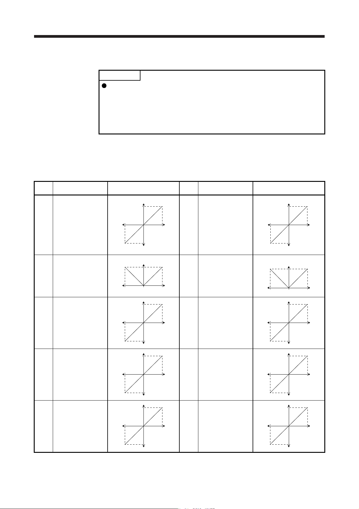
The servo amplifier is factory-set to output the servo motor speed to MO1 (Analog monitor 1) and the
torque to MO2 (Analog monitor 2). The setting can be changed as listed below by setting the [Pr. PC09]
and [Pr. PC10] value.
Refer to (3) for the detection point.
Setting
value
Output item Description
Setting
value
Output item Description
00 Servo motor speed/
Linear servo motor
speed
Maximum speed
CW direction
CCW direction
Maximum speed
0
8 [V]
-8 [V]
01 Torque/Thrust (Note 8)
Maximum torqu
e
Power running i
n
CW direction
Power running i
n
CCW direction
Maximum torque
0
8 [V]
-8 [V]
02 Servo motor speed/
Linear servo motor
speed
Maximum speed
CW direction CCW direction
Maximum speed 0
8 [V]
03 Torque/Thrust (Note 8)
Maximum torqu
e
Power running i
n
CW direction
Power running i
n
CCW direction
Maximum torque 0
8 [V]
04
Current command
(Note 8)
Maximum current command
(Maximum torque command)
CW directio
n
CCW directio
n
Maximum current comman
d
(
Maximum torque comman
d
0
8 [V]
-8 [V]
05 Speed command
Maximum speed
CW directio
n
CCW directio
n
Maximum speed
0
8 [V]
-8 [V]
06
Servo motor-side droop
pulses
(Note 1, 3, 5, 6)
(±10 V/100 pulses)
100 [pulse]
CW directio
n
CCW directio
n
100 [pulse
]
0
10 [V]
-10 [V]
07
Servo motor-side droop
pulses
(Note 1, 3, 5, 6)
(±10 V/1000 pulses)
1000 [pulse]
CW directio
n
CCW directio
n
1000 [pulse
]
0
10 [V]
-10 [V]
08
Servo motor-side droop
pulses
(Note 1, 3, 5, 6)
(±10 V/10000 pulses)
10000 [pulse]
CW directio
n
CCW directio
n
10000 [pulse
]
0
10 [V]
-10 [V]
09
Servo motor-side droop
pulses
(Note 1, 3, 5, 6)
(±10 V/100000 pulses)
100000 [pulse]
CW directio
n
CCW directio
n
100000 [pulse
]
0
10 [V]
-10 [V]