sh030106u.pdf - 第675页
APPENDIX App. - 44 App. 12. 2 Magnetic co ntactor Use the mag netic contact or with an opera tion d elay tim e (inter v al b etween curr ent being app lied to the c oil until closure of c ontacts) of 80 ms or less (160 m…
APPENDIX
App. - 43
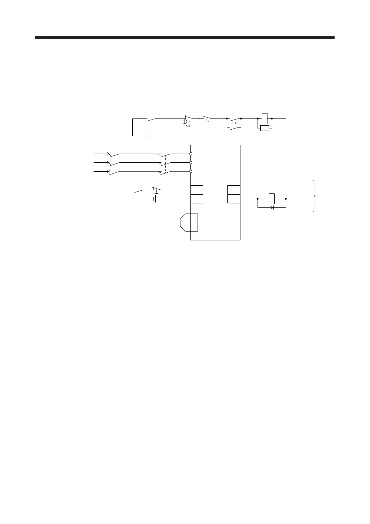
App. 12 Driving on/off of main circuit power supply with DC power supply
App. 12.1 Connection example
The power circuit is common to all capacity type of servo amplifiers. For the signal and wirings not given in
this section, refer to section 3.1.1 to 3.1.3.
MC (Note 3)
ALM
DOCOM
CN3
(Note 2)
24 V DC (Note 6)
24 V DC (Note 6)
24 V DC (Note 7,8)
Malfunction
(Note 9)
RA1
L1
L2
L3
Power supply
(Note 1)
Servo amplifier
Malfunction
RA1
OFF
MC
ON
MC
Emergency stop switch
CN3
(Note 2)
Forced stop 2
EM2
CN8
(Note 5)
Short-circuit connector
(Packed with the servo amplifier)
(Note 4)
Main circuit
power supply
MCCB
SK
DOCOM
Note 1. For the power suppl
y
specifications, refer to section 1.3.
2. This dia
g
ram shows sink I/O interface. For source I/O interface, refer to section 3.9.3.
3. Use the magnetic contactor with an operation delay time (interval between current being applied to the coil until closure of
contacts) of 80 ms or less (160 ms or less for 5 kW or more). Depending on the main circuit voltage and operation pattern, bus
voltage decreases, and that may cause the forced stop deceleration to shift to the dynamic brake deceleration. When dynamic
brake deceleration is not required, slow the time to turn off the ma
g
netic contactor.
4. Configure a circuit to turn off EM2 when the main circuit power is turned off to prevent an unexpected restart of the servo
amplifier.
5. When not usin
g
the STO function, attach the short-circuit connector came with a servo amplifier.
6. The illustration of the 24 V DC power supply is divided between input signal and output signal for convenience. However, they
can be confi
g
ured b
y
one.
7. Drivin
g
the on switch and off switch with the DC power suppl
y
meets IEC/EN 60204-1 requirements.
8. Do not use the 24 V DC interface power supply for the magnetic contactor DC power supply. Always use the power supply
desi
g
ned exclusivel
y
for the ma
g
netic contactor.
9. If ALM (Malfunction) output is disabled with the parameter, configure the power supply circuit which switches off the magnetic
contactor after detection of alarm occurrence on the controller side.
APPENDIX
App. - 44
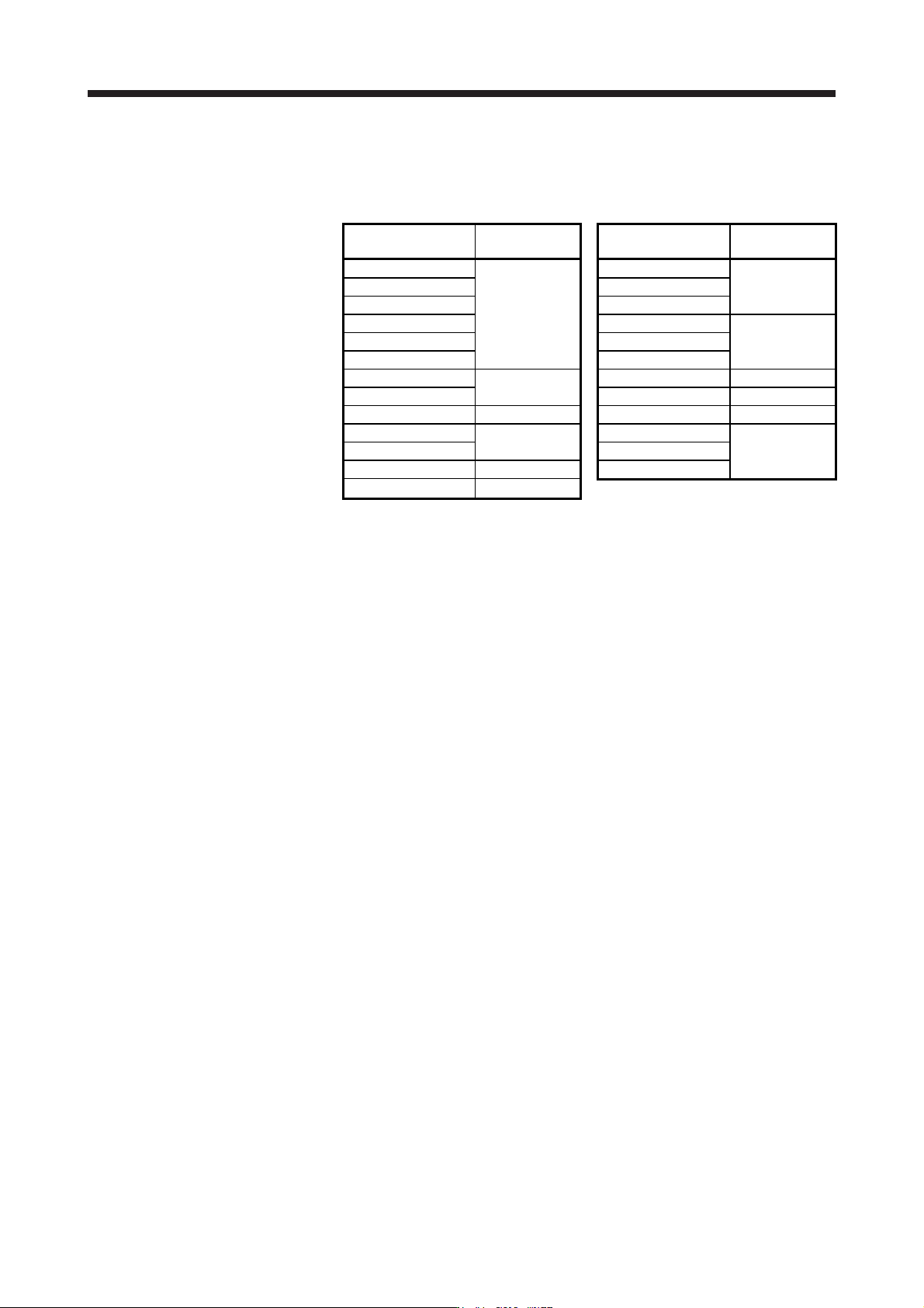
App. 12.2 Magnetic contactor
Use the magnetic contactor with an operation delay time (interval between current being applied to the coil
until closure of contacts) of 80 ms or less (160 ms or less for 5 kW or more).
Servo amplifier
Magnetic
contactor
Servo amplifier
Magnetic
contactor
MR-J4-10B(-RJ) MR-J4-60B4(-RJ)
MR-J4-20B(-RJ) MR-J4-100B4(-RJ) SD-N11
MR-J4-40B(-RJ)
SD-N11
MR-J4-200B4(-RJ)
MR-J4-60B(-RJ) MR-J4-350B4(-RJ)
MR-J4-70B(-RJ) MR-J4-500B4(-RJ) SD-N21
MR-J4-100B(-RJ) MR-J4-700B4(-RJ)
MR-J4-200B(-RJ)
SD-N21
MR-J4-11KB4(-RJ) SD-N25
MR-J4-350B(-RJ) MR-J4-15KB4(-RJ) SD-N35
MR-J4-500B(-RJ) SD-N35 MR-J4-22KB4(-RJ) SD-N50
MR-J4-700B(-RJ)
SD-N50
MR-J4-10B1(-RJ)
MR-J4-11KB(-RJ) MR-J4-20B1(-RJ) SD-N11
MR-J4-15KB(-RJ) SD-N65 MR-J4-40B1(-RJ)
MR-J4-22KB(-RJ) SD-N95

APPENDIX
App. - 45
App. 13 Optional data monitor function
The optional data monitor function is used to monitor data in the servo amplifier with the servo system
controller. In the optional data monitor function, data types of registered monitor and transient command can
be set.
For details of usage, the unit of data types, and others, refer to the manuals for servo system controllers.
App. 13.1 Registered monitor
Data type Description
Effective load ratio The continuous effective load current is displayed.
The effective value is displayed considering a rated current as 100%.
Regenerative load ratio The ratio of regenerative power to permissible regenerative power is displayed in %.
Peak load ratio The maximum torque generated is displayed.
The highest value in the past 15 s is displayed, with the rated torque being 100%.
Position feedback Feedback pulses from the servo motor encoder are counted and displayed.
The "-" symbol is indicated for reverse.
In the fully closed loop control mode, the position within one-revolution is displayed in the
load-side encoder unit after gear.
When the mode is switched to the semi closed loop control mode after the fully closed loop
selection command is turned off, the value in the motor-side encoder unit is displayed.
The displayed range is from -2147483648 pulses to 2147483647 pulses.
Encoder position within one revolution The position in servo motor-side 1-revolution is displayed in the encoder pulse unit.
When the value exceeds the maximum number of pulses, it resets to 0.
Encoder multiple revolution counter
The rotation amount of the servo motor is displayed. The value is counted up by one per
servo motor revolution.
Load inertia moment ratio
The set ratio of the load inertia moment to the servo motor shaft inertia moment is
displayed.
Load to motor mass ratio The load to mass of the linear servo motor primary-side ratio is displayed.
Model loop gain The model loop gain value is displayed.
Main circuit bus voltage The voltage of main circuit converter (between P+ and N-) is displayed.
Cumulative current value The cumulative current value of the servo motor is displayed.
Servo motor speed The servo motor speed is displayed.
Servo motor speed The linear servo motor speed is displayed at linear servo motor driving.
Selected droop pulse The droop pulse set in [Pr. PE10] is displayed.
Module power consumption The module power consumption is displayed.
The positive value is displayed in power running. The negative value is displayed in
regeneration.
Module integral power consumption The module integral power consumption is displayed.
Instantaneous torque The instantaneous torque is displayed.
The value of torque being occurred is displayed in real time considering a rated torque as
100%.
Instantaneous thrust The instantaneous thrust is displayed at linear servo motor driving.
The value of thrust being occurred is displayed in real time considering a continuous thrust
as 100%.
Load-side encoder information 1 (Note)
The item to be displayed depends on the encoder being connected to the load side as
follows.
For a rotary servo motor (HG-KR, HG-MR) or synchronous encoder (Q171ENC-W8), the
cycle counter is displayed.
For an absolute position linear encoder, the absolute position data is displayed.
For an incremental linear encoder, the Z-phase counter (distance from the linear encoder
home position (reference mark)) (32-bit data) is displayed after the Z-phase is passed. The
value before the Z-phase is passed is undefined.
For an A/B/Z-phase differential output linear encoder, the Z-phase counter (distance from
the linear encoder home position (Z-phase)) (16-bit data) is displayed after the Z-phase is
passed. Before the Z-phase is passed, the free-run counter is displayed (the position at
power-on is 0).
For an A/B/Z-phase differential output rotary encoder, the Z-phase counter (distance from
the encoder home position (Z-phase)) (16-bit data) is displayed after the Z-phase is
passed. Before the Z-phase is passed, the free-run counter is displayed (the position at
power-on is 0).