sh030106u.pdf - 第689页
APPENDIX App. - 58 MEMO
APPENDIX
App. - 57
App. 17 Encoder output pulse setting method
POINT
Depending on the servo motor stop position, the encoder output pulse may turn
on and off repeatedly even if the servo motor is stopped.
For details of "Encoder output pulse setting selection" in [Pr. PC19], refer to the following table.
Setting value Servo motor/direct drive motor Linear servo motor
_ _ 0 _
(Output pulse
setting)
Set the output pulses per revolution with [Pr. PA15
Encoder output pulses].
Output pulse = a value set in [Pr. PA15] [pulse/rev]
Selecting "Load side encoder (_ 1 _ _)" of "Encoder
selection for encoder output pulse" in [Pr. PC19] triggers
[AL. 37 Parameter error].
The output pulse setting cannot be used. If "0" is selected,
the dividing ratio setting is used.
_ _1 _
(Dividing ratio
setting)
Set the dividing ratio to the resolution per servo motor
revolution with [Pr. PA15 Encoder output pulses].
Output pulse =
Resolution per revolution
[Pr. PA15] setting
[pulse/rev]
Set the dividing ratio to the travel distance of the linear
servo motor with [Pr. PA15 Encoder output pulses].
Output pulse =
Travel distance of linear servo motor
[Pr. PA15] setting
[pulse]
_ _ 2 _
(The same
output pulse
setting as the
command
pulse)
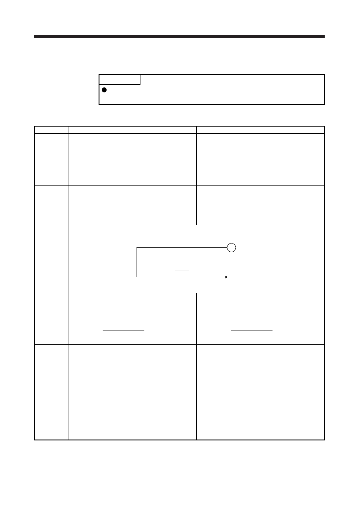
Feedback pulses from the encoder are processed as follows to be outputted. Feedback pulses are outputted in the
same pulse unit as the command pulse.
Encoder
CDV
CMX
Feedback pulse
Output puls
e
[Pr. PA06]/[Pr. PA07]
_ _ 3 _
(A-phase/B-
phase pulse
electronic
gear setting)
Set the A-phase/B-phase pulse electronic gear with [Pr.
PA15 Encoder output pulses] and [Pr. PA16 Encoder
output pulses 2].
Output pulse = the servo motor resolution per revolution ×
[Pr. PA15] setting
[Pr. PA16] setting
[pulse/rev]
Set the A-phase/B-phase pulse electronic gear with [Pr.
PA15 Encoder output pulses] and [Pr. PA16 Encoder
output pulses 2].
Output pulse = Travel direction of linear servo motor ×
[Pr. PA15] setting
[Pr. PA16] setting
[pulse]
_ _ 4 _
(A/B-phase
pulse through
output
setting)
[AL. 37 Parameter error] occurs.
A/B-phase pulse of A/B/Z-phase differential output
encoder is outputted. This is enabled only when A/B/Z-
phase differential output encoder is used.
Output pulse = A/B-phase pulse of A/B/Z-phase
differential output encoder [pulse]
The value set for "Encoder output pulse phase selection"
in [Pr. PC19] is not applied.
When another encoder is connected, [AL. 37 Parameter
error] occurs. Selecting "Standard control mode (_ _ 0 _)"
of "Operation mode" in [Pr. PA01] triggers [AL. 37
Parameter error].
The values set for [Pr. PA15 Encoder output pulses] and
[Pr. PA16 Encoder output pulses 2] are not applied.

APPENDIX
App. - 58
MEMO

REV
ISION
*The manual number is given on the bottom left of the back cove
r.
Revision Date *Manual Numbe
r
Revision
Mar. 2012 SH
(
NA
)
030106ENG-
A
First edition
Jun. 2012 SH(NA)030106ENG-B 4. Additional instructions
(2) Wiri
ng
4.
Additional instructi
ons
(3)
Test run and adjustment
COMPLIANCE WITH
CE
MARKING
COMPLIANCE WITH
UL/CSA STANDARD
COMPLIANCE WITH KC
MARK
Section 1.2
S
ection 1.
3
S
ection 1.
5
S
ection 1.7.1
Chapter 2
Section 2.5
Section 2.6
Chapter 3
Section 3.1
Section 3.1.1 (1)
Section 3.1.1 (2)
Section 3.1.1 (3)
Section 3.1.1 (4)
Section 3.2.1
Section 3.2.2
Section 3.3.1
Section 3.3.3 (2) (a)
Section 3.5.2 (2)
Section 3.6.2 (1)
Section 3.7.1 (3)
Section 3.8.2 (1)
Section 3.8.2 (2)
Section 3.8.3 (1)
Section 3.8.3 (2)
Section 3.10.2 (1) (a)
Section 4.1.2 (1) (b) 4)
Section 4.3.3 (1)
Section 4.5.2 (1) (b)
Section 5.1
Section 5.1.1
Section 5.1.6
Section 5.2.1
Section 5.2.3
Section 5.2.4
Section 5.2.5
Section 5.2.6
Chapter 6
The sentences are added.
The sentences are added.
The reference is changed.
The reference is changed.
Added.
The diagram is changed.
The table and Note are changed.
The sentences of the fully closed loop system and drive
recorder are changed.
The diagram is changed.
CAUTION is changed.
POINT is changed to CAUTION.
The explanation of relay lifetime is changed.
The sentences are added to CAUTION.
The sentences are added to CAUTION.
Note 12 is added.
Note 11 is added.
Note 11 is added.
Note 11 is added.
Note 11 is added.
Note 17 is added.
Note 17 is added.
The sentences of N- are changed.
The ferrule is added.
The sentences of INP (In-position) are added.
CLDS (During fully closed loop control) is added.
The sentences are added.
The sentences are added.
The sentences are changed.
The sentences are added.
The sentences are added.
The sentences are added.
The sentences are changed.
Added.
The diagram is changed.
Note is added. [AL. 20 Encoder normal communication error 1
(ABZ input)] in the table is deleted.
POINT is changed and Note is deleted.
PA25 is changed from "For manufacturer setting".
PF06 and PF12 are changed from "For manufacturer setting".
The sentences are added to PA01 and PA25 is added.
The sentences of PC01 are changed and sentences are
added to PC03.
The table of PD07 is changed.
The sentences are added to PE08.
PF06 and PF12 are added.
The sentences in POINT are chan
g
ed.