sh030106u.pdf - 第70页
2. INSTALLATION 2 - 1 2. INSTALLATION WARNING To prevent electr ic shock , ground each e quipment s ecur ely. CAUTION Stacking i n exces s of the s pecif ied num ber o f product pack ages is not al lowed. Do not hold the…
1. FUNCTIONS AND CONFIGURATION
1 - 52
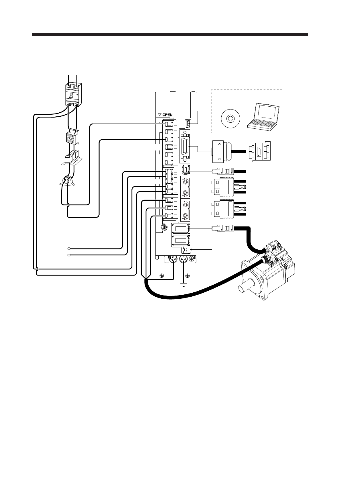
(3) 100 V class
The diagram is for MR-J4-20B1-RJ.
CN4
CN5
P+
C
L11
L21
MR Configurator2
CN3
CN8
CN1A
CN1B
CN2
CN2L (Note 4)
W
V
U
L1
L2
RT
Line noise
filter
(FR-BSF01)
Regenerative
option
Servo motor
Personal
computer
Magnetic
contactor
(MC)
(Note 3)
(Note 1)
Junction terminal
block
To safety relay or MR-J3-D05
safety logic unit
Servo system controller or
previous servo amplifier
CN1B
Next servo amplifier CN1A or
cap
Battery
Molded-case
circuit breaker
(MCCB)
Power supply
(Note 2)
Power factor
improving AC
reactor
(FR-HAL)
(Note 1)
D (Note 5)
Note 1. The power factor improvin
g
DC reactor cannot be used.
2. For power suppl
y
specifications, refer to section 1.3.
3. Depending on the main circuit voltage and operation pattern, bus voltage decreases, and that may cause the forced stop
deceleration to shift to the dynamic brake deceleration. When dynamic brake deceleration is not required, slow the time to turn
off the ma
g
netic contactor.
4. This is for MR-J4-_B1-RJ servo amplifier. MR-J4-_B1 servo amplifier does not have CN2L connector. Refer to Table 1.1 and
Linear Encoder Instruction Manual for the compatible external encoders.
5.
A
lwa
y
s connect between P+ and D terminals. When usin
g
the re
g
enerative option, refer to section 11.2.
2. INSTALLATION
2 - 1
2. INSTALLATION
WARNING
To prevent electric shock, ground each equipment securely.
CAUTION
Stacking in excess of the specified number of product packages is not allowed.
Do not hold the front cover, cables, or connectors when carrying the servo
amplifier. Otherwise, it may drop.
Install the equipment on incombustible material. Installing it directly or close to
combustibles will lead to a fire.
Install the servo amplifier and the servo motor in a load-bearing place in
accordance with the Instruction Manual.
Do not get on or put heavy load on the product. Otherwise, it may cause injury.
Use the equipment within the specified environment. For the environment, refer to
section 1.3.
Provide an adequate protection to prevent screws and other conductive matter, oil
and other combustible matter from entering the servo amplifier.
Do not block the intake and exhaust areas of the servo amplifier. Otherwise, it
may cause a malfunction.
Do not drop or apply heavy impact on the servo amplifiers and the servo motors.
Otherwise, injury, malfunction, etc. may occur.
Do not install or operate the servo amplifier which have been damaged or have
any parts missing.
When the product has been stored for an extended period of time, contact your
local sales office.
When handling the servo amplifier, be careful about the edged parts such as
corners of the servo amplifier.
The servo amplifier must be installed in the metal cabinet.
Fumigants that are used to disinfect and protect wooden packaging from insects
contain halogens (such as fluorine, chlorine, bromine, and iodine) cause damage
if they enter our products. Please take necessary precautions to ensure that
remaining materials from fumigant do not enter our products, or treat packaging
with methods other than fumigation (heat method).Additionally, disinfect and
protect wood from insects before packing products.
POINT
When pulling out CNP1, CNP2, and CNP3 connectors of 100 V class/600 W or
lower 200 V class servo amplifier, pull out CN3 and CN8 connectors beforehand.
2. INSTALLATION
2 - 2
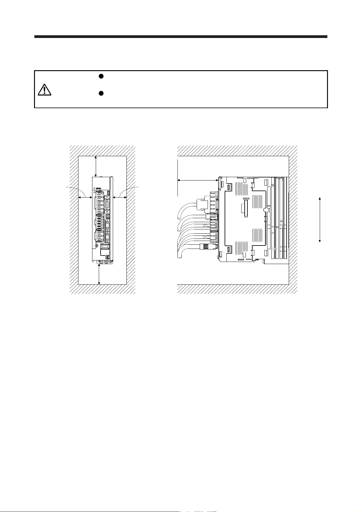
2.1 Installation direction and clearances
CAUTION
The equipment must be installed in the specified direction. Otherwise, it may
cause a malfunction.
Leave specified clearances between the servo amplifier and the cabinet walls or
other equipment. Otherwise, it may cause a malfunction.
(1) Installation clearances of the servo amplifier
(a) Installation of one servo amplifier
40 mm or more
10 mm
or more
10 mm
or more
(Note 2)
40 mm
or more
(Note 1)
Servo amplifier
Cabinet Cabinet
Wiring allowance
80 mm or more
Top
Bottom
Note 1. For 11 kW to 22 kW servo amplifiers, the clearance between the bottom and
g
round will be 120 mm or more.
2. When mountin
g
MR-J4-500B
(
-RJ
)
, maintain a minimum clearance of 25 mm on the left side.