sh030106u.pdf - 第75页
2. INSTALLATION 2 - 6 (5) Tension If tension is ad ded on optical c able, the incr ease of tr a nsmiss ion loss occurs bec ause of external force which co ncentrat es on the f ixing par t of o ptical f iber or the connec…
2. INSTALLATION
2 - 5
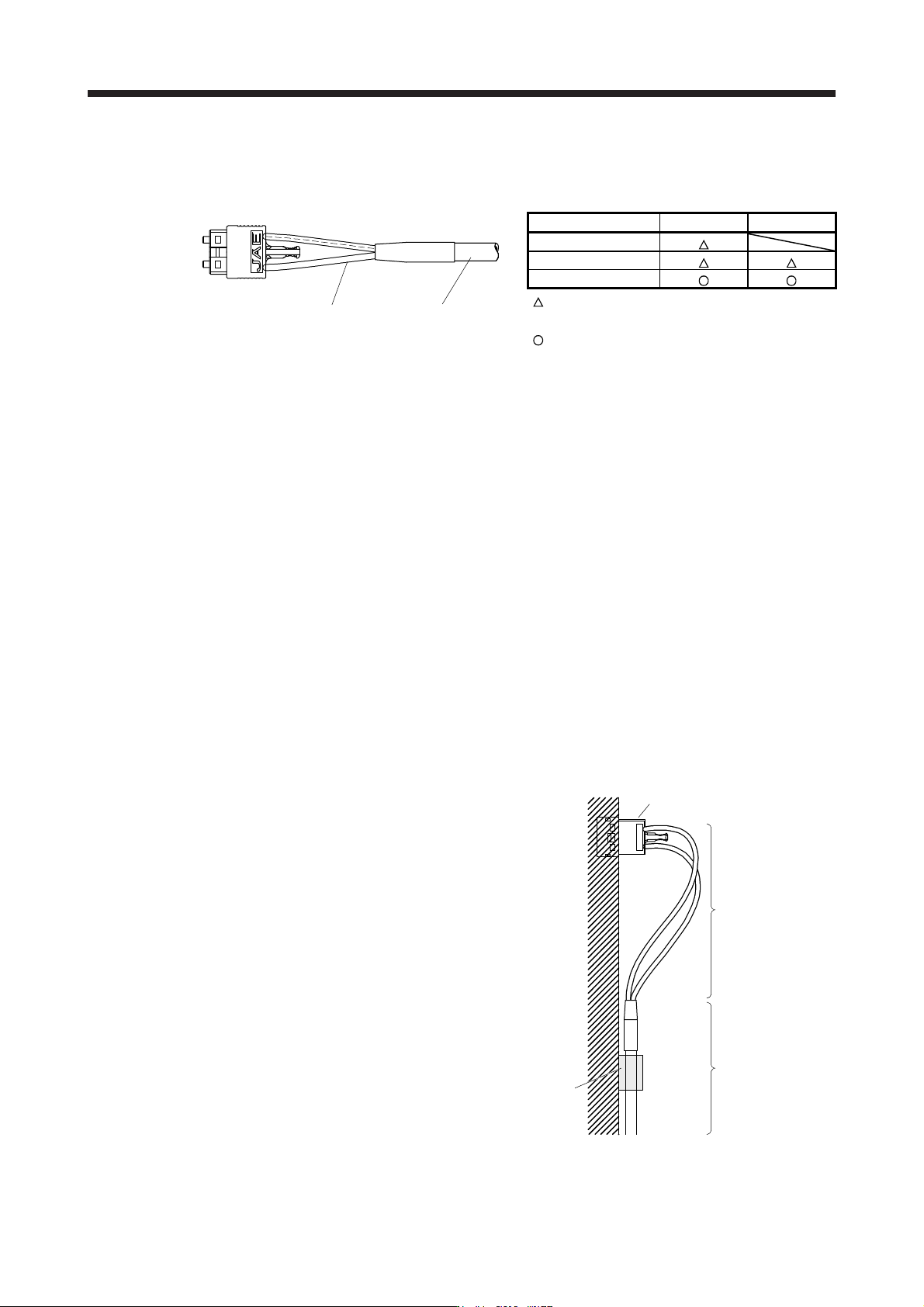
(2) Prohibition of vinyl tape use
Migrating plasticizer is used for vinyl tape. Keep the MR-J3BUS_M, and MR-J3BUS_M-A cables away
from vinyl tape because the optical characteristic may be affected.
Optical cord
Cable
SSCNET III cable Cord Cable
MR-J3BUS_M
MR-J3BUS_M-A
MR-J3BUS_M-B
: Phthalate ester plasticizer such as DBP and DOP
may affect optical characteristic of cable.
: Cord and cable are not basically affected by
plasticizer.
(3) Precautions for migrating plasticizer added materials
Generally, soft polyvinyl chloride (PVC), polyethylene resin (PE) and fluorine resin contain non-migrating
plasticizer and they do not affect the optical characteristic of SSCNET III cable. However, some wire
sheaths and cable ties, which contain migrating plasticizer (phthalate ester), may affect MR-J3BUS_M
and MR-J3BUS_M-A cables (plastic).
In addition, MR-J3BUS_M-B cable (silica glass) is not affected by plasticizer.
A chemical substance may affect its optical characteristic. Therefore, previously check that the cable is
not affected by the environment.
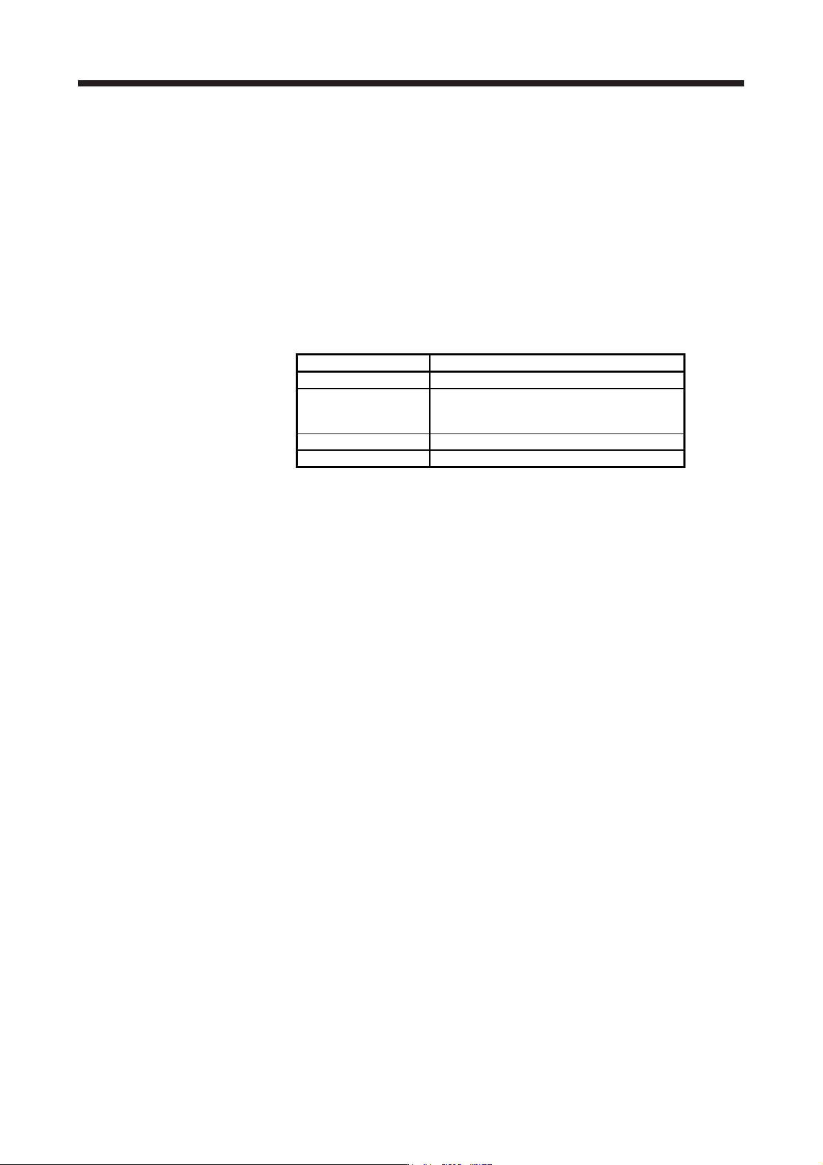
(4) Bundle fixing
Fix the cable at the closest part to the connector with bundle material in order to prevent SSCNET III
cable from putting its own weight on CN1A/CN1B connector of servo amplifier. Optical cord should be
given loose slack to avoid from becoming smaller than the minimum bend radius, and it should not be
twisted.
When bundling the cable, fix and hold it in position by using cushioning such as sponge or rubber which
does not contain migratable plasticizers.
If adhesive tape for bundling the cable is used, fire resistant acetate cloth adhesive tape 570F (Teraoka
Seisakusho Co., Ltd) is recommended.
Optical cord
Loose slack
Bundle material
Recommended product: NK clamp SP type
(NIX, INC)
Cable
Connector
2. INSTALLATION
2 - 6
(5) Tension
If tension is added on optical cable, the increase of transmission loss occurs because of external force
which concentrates on the fixing part of optical fiber or the connecting part of optical connector. Doing so
may cause the breakage of the optical fiber or damage of the optical connector. For cable laying, handle
without putting forced tension. For the tension strength, refer to section 11.1.3.
(6) Lateral pressure
If lateral pressure is added on optical cable, the optical cable itself distorts, internal optical fiber gets
stressed, and then transmission loss will increase. Doing so may cause the breakage of the optical
cable. As the same condition also occurs at cable laying, do not tighten up optical cable with a thing
such as nylon band (cable tie).
Do not trample it down or tuck it down with the door of cabinet or others.
(7) Twisting
If optical fiber is twisted, it will become the same stress added condition as when local lateral pressure or
bend is added. Consequently, transmission loss increases, and the breakage of optical fiber may occur.
(8) Disposal
When incinerating optical cable (cord) used for SSCNET III, hydrogen fluoride gas or hydrogen chloride
gas which is corrosive and harmful may be generated. For disposal of optical fiber, request for
specialized industrial waste disposal services who has incineration facility for disposing hydrogen
fluoride gas or hydrogen chloride gas.
2.5 Inspection items
WARNING
Before starting maintenance and/or inspection, turn off the power and wait for 15
minutes or more until the charge lamp turns off. Then, confirm that the voltage
between P+ and N- is safe with a voltage tester and others. Otherwise, an electric
shock may occur. In addition, when confirming whether the charge lamp is off or
not, always confirm it from the front of the servo amplifier.
To avoid an electric shock, only qualified personnel should attempt inspections.
For repair and parts replacement, contact your local sales office.
CAUTION
Do not perform insulation resistance test on the servo amplifier. Otherwise, it may
cause a malfunction.
Do not disassemble and/or repair the equipment on customer side.
It is recommended that the following points periodically be checked.
(1) Check for loose terminal block screws. Retighten any loose screws.
(2) Check the cables and the like for scratches or cracks. Inspect them periodically according to operating
conditions especially when the servo motor is movable.
(3) Check that the connector is securely connected to the servo amplifier.
(4) Check that the wires are not coming out from the connector.
2. INSTALLATION
2 - 7
(5) Check for dust accumulation on the servo amplifier.
(6) Check for unusual noise generated from the servo amplifier.
(7) Make sure that the emergency stop circuit operates properly such that an operation can be stopped
immediately and a power is shut off by the emergency stop switch.
2.6 Parts having service life
Service life of the following parts is listed below. However, the service life varies depending on operation and
environment. If any fault is found in the parts, they must be replaced immediately regardless of their service
life. For parts replacement, please contact your local sales office.
Part name Life guideline
Smoothing capacitor 10 years
Relay
Power-on, dynamic brake stop, and forced stop
100,000 times
Number of on and off for STO: 1,000,000 times
Cooling fan 10,000 hours to 30,000 hours (2 years to 3 years)
Absolute position battery Refer to section 12.2.
(1) Smoothing capacitor
The characteristic of smoothing capacitor is deteriorated due to ripple currents, etc. The life of the
capacitor greatly depends on ambient temperature and operating conditions. The capacitor will reach the
end of its life in 10 years of continuous operation in air-conditioned environment (ambient temperature of
40 °C or less).
(2) Relays
Contact faults occur due to contact wear arisen from switching currents. A relay will reach the end of its
service life if the following actions are performed a total of 100,000 times: powering on the servo
amplifier, inputting the dynamic brake stop, and inputting the forced stop; or if the following action is
performed a total of 1,000,000 times: turning on or off STO during servo-off and servo motor stop. In
addition, the service life of a relay may vary depending on the power supply capacity.
(3) Servo amplifier cooling fan
The cooling fan bearings reach the end of their life in 10,000 hours to 30,000 hours. Normally, therefore,
the cooling fan must be replaced in a few years of continuous operation as a guideline. If unusual noise
or vibration is found during inspection, the cooling fan must also be replaced.
The life indicates under the yearly average ambient temperature of 40 ˚C, free from corrosive gas,
flammable gas, oil mist, dust and dirt.