sh030106u.pdf - 第77页
2. INSTALLATION 2 - 8 2.7 Restr ictions when usi ng this pr oduct a t altit ude ex ceeding 100 0 m and up to 2000 m abov e sea lev el (1) Effectiv e load r atio and r egenerat ive load ratio As heat d issipat ion eff ect…
2. INSTALLATION
2 - 7
(5) Check for dust accumulation on the servo amplifier.
(6) Check for unusual noise generated from the servo amplifier.
(7) Make sure that the emergency stop circuit operates properly such that an operation can be stopped
immediately and a power is shut off by the emergency stop switch.
2.6 Parts having service life
Service life of the following parts is listed below. However, the service life varies depending on operation and
environment. If any fault is found in the parts, they must be replaced immediately regardless of their service
life. For parts replacement, please contact your local sales office.
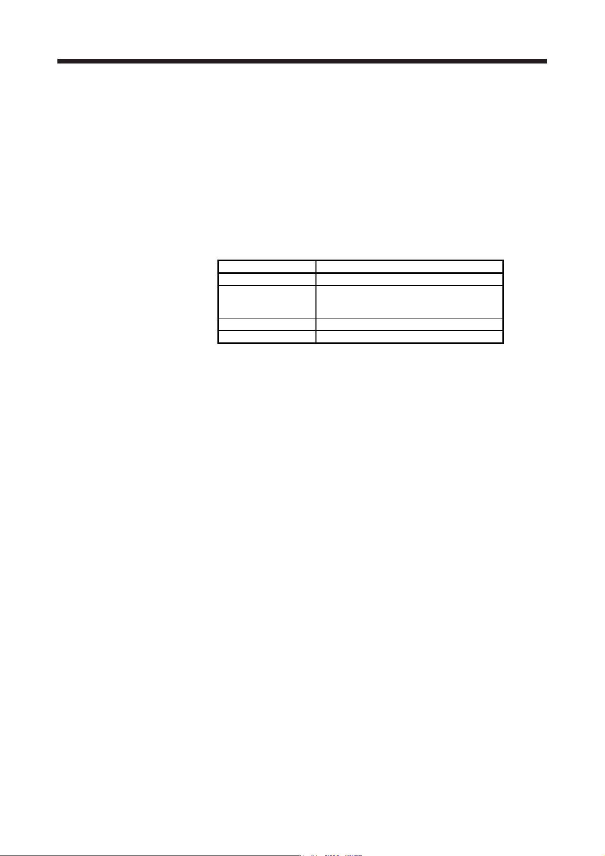
Part name Life guideline
Smoothing capacitor 10 years
Relay
Power-on, dynamic brake stop, and forced stop
100,000 times
Number of on and off for STO: 1,000,000 times
Cooling fan 10,000 hours to 30,000 hours (2 years to 3 years)
Absolute position battery Refer to section 12.2.
(1) Smoothing capacitor
The characteristic of smoothing capacitor is deteriorated due to ripple currents, etc. The life of the
capacitor greatly depends on ambient temperature and operating conditions. The capacitor will reach the
end of its life in 10 years of continuous operation in air-conditioned environment (ambient temperature of
40 °C or less).
(2) Relays
Contact faults occur due to contact wear arisen from switching currents. A relay will reach the end of its
service life if the following actions are performed a total of 100,000 times: powering on the servo
amplifier, inputting the dynamic brake stop, and inputting the forced stop; or if the following action is
performed a total of 1,000,000 times: turning on or off STO during servo-off and servo motor stop. In
addition, the service life of a relay may vary depending on the power supply capacity.
(3) Servo amplifier cooling fan
The cooling fan bearings reach the end of their life in 10,000 hours to 30,000 hours. Normally, therefore,
the cooling fan must be replaced in a few years of continuous operation as a guideline. If unusual noise
or vibration is found during inspection, the cooling fan must also be replaced.
The life indicates under the yearly average ambient temperature of 40 ˚C, free from corrosive gas,
flammable gas, oil mist, dust and dirt.
2. INSTALLATION
2 - 8
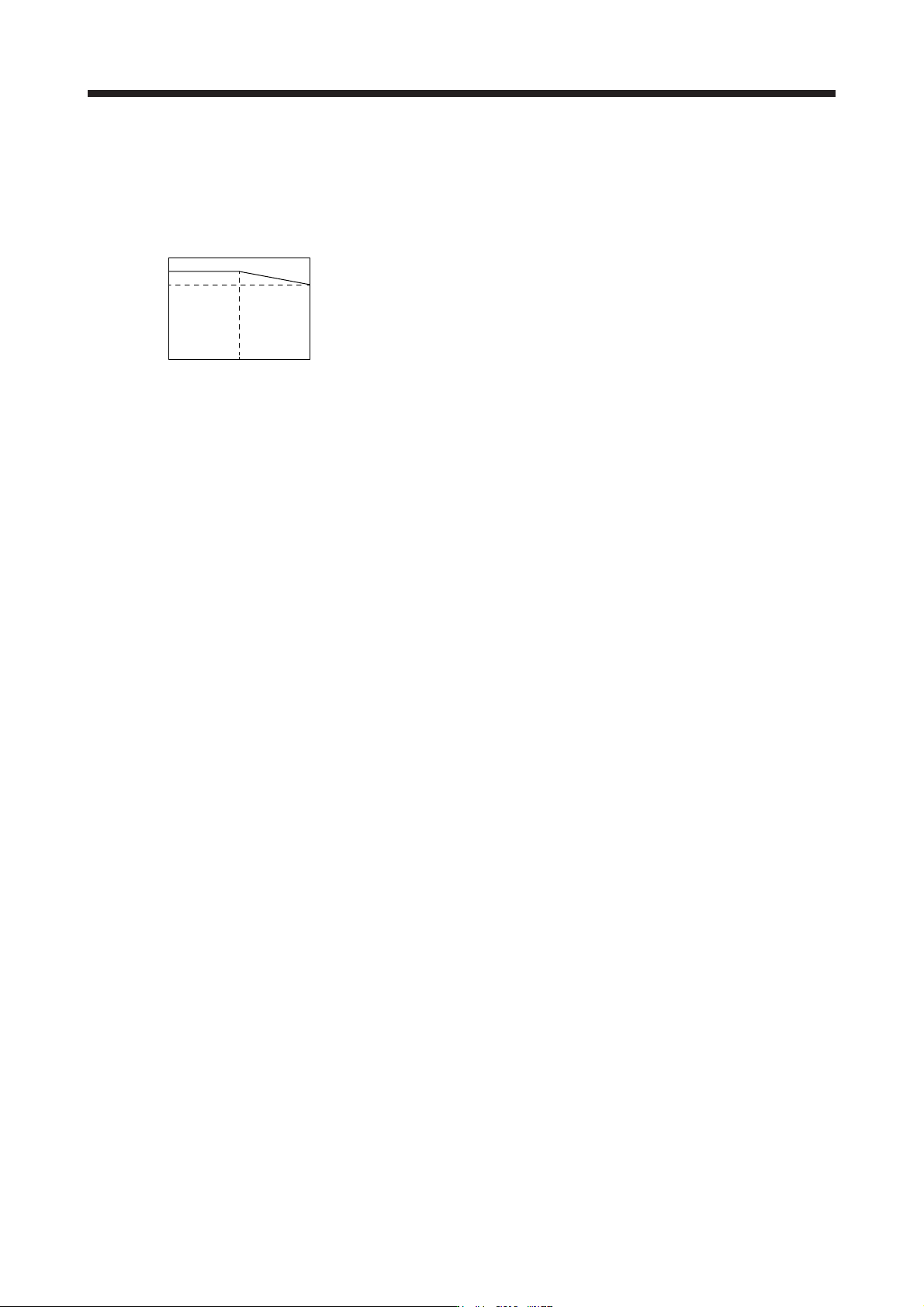
2.7 Restrictions when using this product at altitude exceeding 1000 m and up to 2000 m above sea level
(1) Effective load ratio and regenerative load ratio
As heat dissipation effects decrease in proportion to the decrease in air density, use the product within
the effective load ratio and regenerative load ratio shown in the following figure.
0
20001000
Altitude
95
100
0
Regenerative load ratio
Effective load ratio
[%]
[m]
When closely mounting the servo amplifiers, operate them at the ambient temperature of 0 °C to 45 °C
or at 75% or smaller effective load ratio. (Refer to section 2.1.)
(2) Input voltage
Generally, a withstand voltage decreases as increasing altitude; however, there is no restriction on the
withstand voltage. Use in the same manner as in 1000 m or less. (Refer to section 1.3.)
(3) Parts having service life
(a) Smoothing capacitor
The capacitor will reach the end of its life in 10 years of continuous operation in air-conditioned
environment (ambient temperature of 30 °C or less).
(b) Relay
There is no restriction. Use in the same manner as in 1000 m or less. (Refer to section 2.6.)
(c) Servo amplifier cooling fan
There is no restriction. Use in the same manner as in 1000 m or less. (Refer to section 2.6.)
3. SIGNALS AND WIRING
3 - 1
3. SIGNALS AND WIRING
WARNING
Any person who is involved in wiring should be fully competent to do the work.
Before wiring, turn off the power and wait for 15 minutes or more until the charge
lamp turns off. Then, confirm that the voltage between P+ and N- is safe with a
voltage tester and others. Otherwise, an electric shock may occur. In addition,
when confirming whether the charge lamp is off or not, always confirm it from the
front of the servo amplifier.
Ground the servo amplifier and servo motor securely.
Do not attempt to wire the servo amplifier and servo motor until they have been
installed. Otherwise, it may cause an electric shock.
The cables should not be damaged, stressed, loaded, or pinched. Otherwise, it
may cause an electric shock.
To avoid an electric shock, insulate the connections of the power supply terminals.
CAUTION
Wire the equipment correctly and securely. Otherwise, the servo motor may
operate unexpectedly, resulting in injury.
Connect cables to the correct terminals. Otherwise, a burst, damage, etc. may
occur.
Ensure that polarity (+/-) is correct. Otherwise, a burst, damage, etc. may occur.
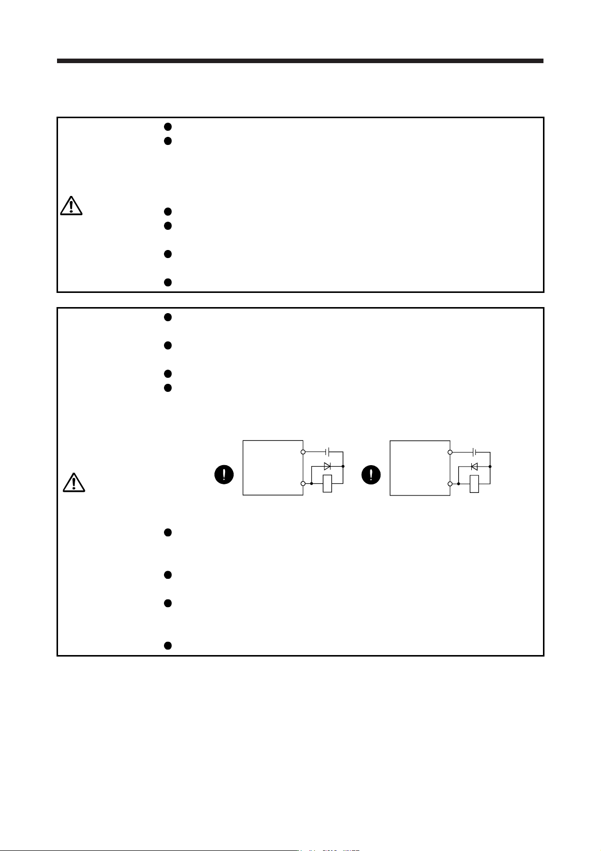
The surge absorbing diode installed to the DC relay for control output should be
fitted in the specified direction. Otherwise, the emergency stop and other
protective circuits may not operate.
DOCOM
24 V DC
Servo amplifier
RA
For sink output interface
Control output
signal
DOCOM
Control output
signal
24 V DC
Servo amplifier
RA
For source output interface
Use a noise filter, etc. to minimize the influence of electromagnetic interference.
Electromagnetic interference may be given to the electronic equipment used near
the servo amplifier.
Do not install a power capacitor, surge killer or radio noise filter (optional FR-BIF(-
H)) with the power line of the servo motor.
When using the regenerative resistor, switch power off with the alarm signal.
Otherwise, a transistor fault or the like may overheat the regenerative resistor,
causing a fire.
Do not modify the equipment.