sh030106u.pdf - 第8页
A - 7 EEP-ROM l ife The number of wr ite tim es t o the E EP-ROM, wh ich stores paramete r s ettings , etc., is limited to 100, 000. If the total nu mber of the f ollowing operati ons exc eeds 1 00,000, t he servo a mpli…
A - 6
(5) Corrective actions
CAUTION
Ensure safety by confirming the power off, etc. before performing corrective actions. Otherwise, it may
cause an accident.
If it is assumed that a power failure, machine stoppage, or product malfunction may result in a hazardous
situation, use a servo motor with an electromagnetic brake or provide an external brake system for
holding purpose to prevent such hazard.
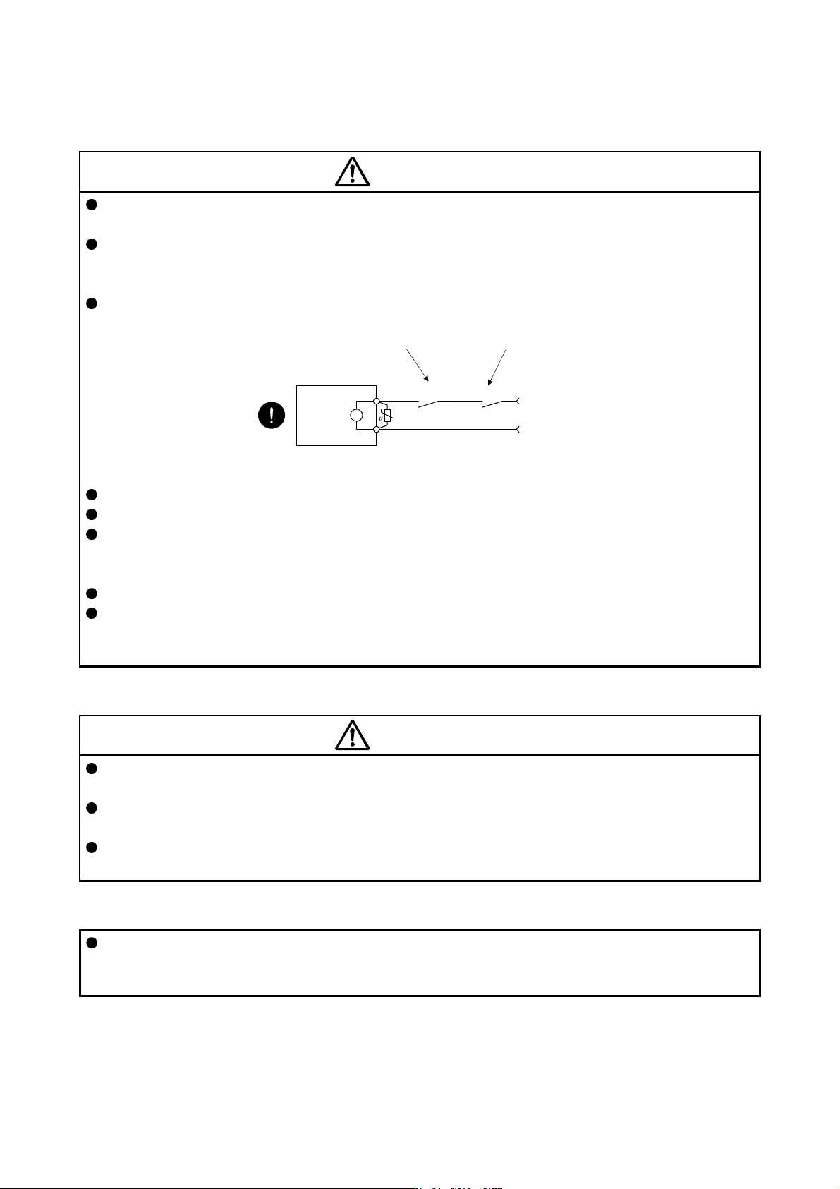
Configure an electromagnetic brake circuit which is interlocked with an external emergency stop switch.
Servo motor
Electromagnetic brake
B
RA
Contacts must be opened with
the emergency stop switch.
Contacts must be opened when ALM
(Malfunction) or MBR (Electromagnetic
brake interlock) turns off.
24 V DC
Failure of MBR (Electromagnetic brake interlock) or ALM (Malfunction) may cause brake malfunction.
When an alarm occurs, eliminate its cause, ensure safety, and deactivate the alarm to restart operation.
If the molded-case circuit breaker or fuse is activated, be sure to remove the cause and secure safety
before switching the power on. If necessary, replace the servo amplifier and recheck the wiring.
Otherwise, it may cause smoke, fire, or an electric shock.
Provide an adequate protection to prevent unexpected restart after an instantaneous power failure.
After an earthquake or other natural disasters, ensure safety by checking the conditions of the
installation, mounting, wiring, and equipment before switching the power on to prevent an electric shock,
injury, or fire.
(6) Maintenance, inspection and parts replacement
CAUTION
Make sure that the emergency stop circuit operates properly such that an operation can be stopped
immediately and a power is shut off by the emergency stop switch.
It is recommended that the servo amplifier be replaced every 10 years when it is used in general
environment.
When using the servo amplifier that has not been energized for an extended period of time, contact your
local sales office.
(7) General instruction
To illustrate details, the equipment in the diagrams of this Instruction Manual may have been drawn
without covers and safety guards. When the equipment is operated, the covers and safety guards must
be installed as specified. Operation must be performed in accordance with this Instruction Manual.
A - 7
EEP-ROM life
The number of write times to the EEP-ROM, which stores parameter settings, etc., is limited to 100,000. If
the total number of the following operations exceeds 100,000, the servo amplifier may malfunction when the
EEP-ROM reaches the end of its useful life.
Write to the EEP-ROM due to parameter setting changes
Write to the EEP-ROM due to device changes
STO function of the servo amplifier
The servo amplifier complies with safety integrity level 3 (SIL 3) of the IEC 61508:2010 functional safety
standard.
Refer to app. 14 for schedule.
When using the STO function of the servo amplifier, refer to chapter 13.
For the MR-J3-D05 safety logic unit, refer to app. 5.
Compliance with global standards
For the compliance with global standards, refer to app. 4.
«About the manuals»
You must have this Instruction Manual and the following manuals to use this servo. Ensure to prepare
them to use the servo safely.
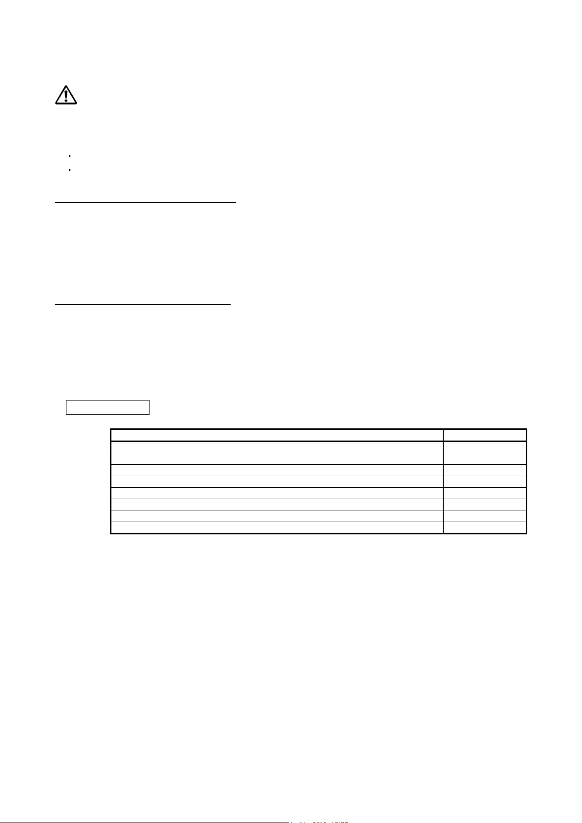
Relevant manuals
Manual name Manual No.
MELSERVO MR-D30 Instruction Manual (Note 5) SH(NA)030132ENG
MELSERVO MR-CV_/MR-CR55K_/MR-J4-DU_(-RJ) Instruction Manual (Note 6) SH(NA)030153ENG
MELSERVO-J4 Servo Amplifier Instruction Manual (Troubleshooting) SH(NA)030109ENG
MELSERVO Servo Motor Instruction Manual (Vol. 3) (Note 1) SH(NA)030113ENG
MELSERVO Linear Servo Motor Instruction Manual (Note 2) SH(NA)030110ENG
MELSERVO Direct Drive Motor Instruction Manual (Note 3) SH(NA)030112ENG
MELSERVO Linear Encoder Instruction Manual (Note 2, 4) SH(NA)030111ENG
MELSERVO EMC Installation Guidelines IB(NA)67310ENG
Note 1. It is necessar
y
for usin
g
a rotar
y
servo motor.
2. It is necessar
y
for usin
g
a linear servo motor.
3. It is necessar
y
for usin
g
a direct drive motor.
4. It is necessar
y
for usin
g
a full
y
closed loop s
y
stem.
5. It is necessar
y
for usin
g
an MR-D30 functional safet
y
unit.
6. It is necessary for using an MR-CV_ power regeneration converter unit/MR-CR_ resistance regeneration
converter unit, and MR-J4-DU_B_
(
-RJ
)
drive unit.
A - 8
«Wiring»
Wires mentioned in this Instruction Manual are selected based on the ambient temperature of 40 °C.
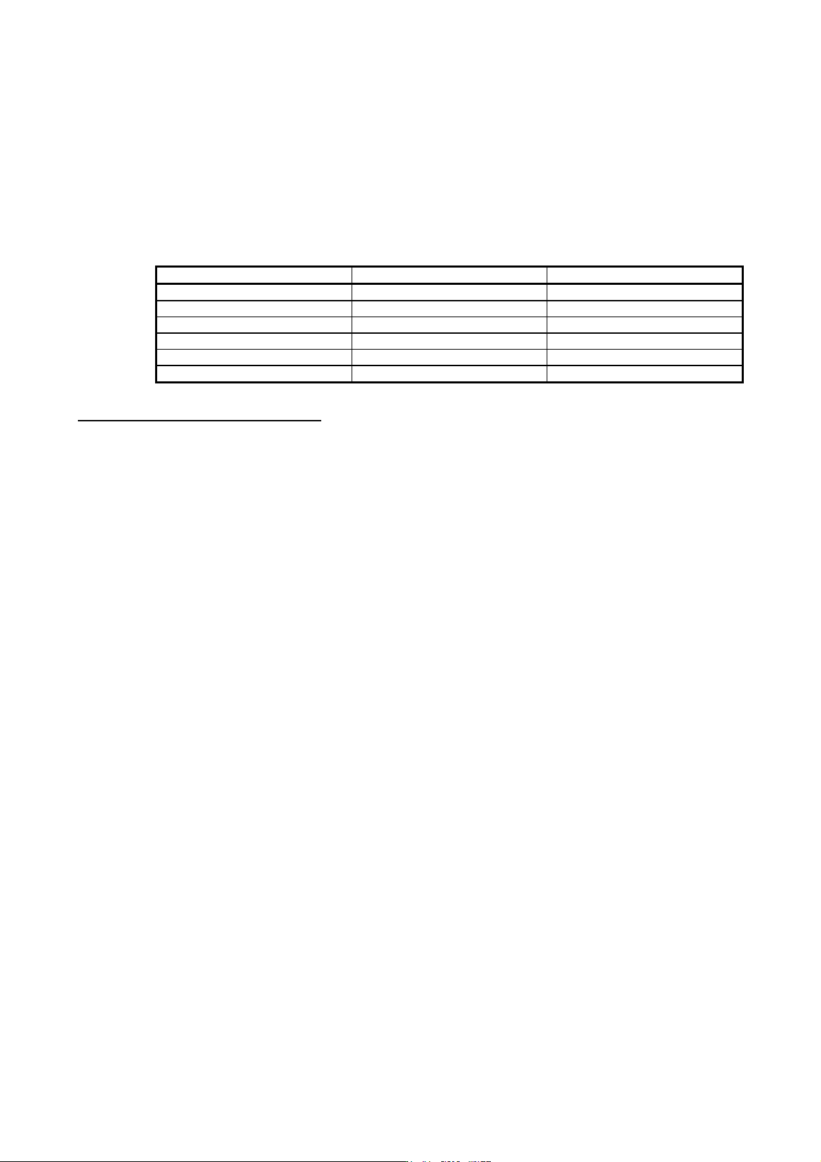
«U.S. customary units»
U.S. customary units are not shown in this manual. Convert the values if necessary according to the
following table.
Quantity SI (metric) unit U.S. customary unit
Mass 1 [kg] 2.2046 [lb]
Length 1 [mm] 0.03937 [inch]
Torque 1 [N•m] 141.6 [oz•inch]
Moment of inertia 1 [(× 10
-4
kg•m
2
)] 5.4675 [oz•inch
2
]
Load (thrust load/axial load) 1 [N] 0.2248 [lbf]
Temperature N [°C] × 9/5 + 32 N [°F]
Global standards and regulations
Compliance with the indicated global standards and regulations is current as of the release date of this
manual. Some standards and regulations may have been modified or withdrawn.