sh030106u.pdf - 第81页
3. SIG NALS A ND WIRI NG 3 - 4 3.1.1 200 V c lass (1) Using 3- phase 200 V AC t o 240 V AC power supply for MR- J4-1 0B(-RJ) to MR-J4-350B(-RJ) ALM DOCOM CN3 RA1 L1 L2 L3 P3 P4 P+ L11 L21 N- D C U V W CNP1 CNP3 CNP2 U V …
3. SIGNALS AND WIRING
3 - 3
3.1 Input power supply circuit
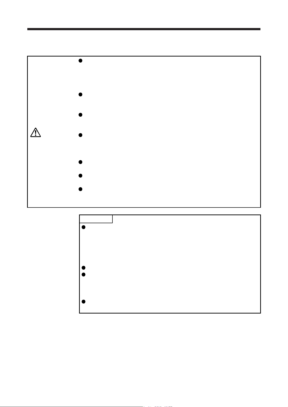
CAUTION
Always connect a magnetic contactor between the power supply and the main
circuit power supply (L1/L2/L3) of the servo amplifier, in order to configure a circuit
that shuts down the power supply on the side of the servo amplifier’s power
supply. If a magnetic contactor is not connected, continuous flow of a large
current may cause a fire when the servo amplifier malfunctions.
Use ALM (Malfunction) to switch main circuit power supply off. Not doing so may
cause a fire when a regenerative transistor malfunctions or the like may overheat
the regenerative resistor.
Check the servo amplifier model, and then input proper voltage to the servo
amplifier power supply. If input voltage exceeds the upper limit, the servo amplifier
will break down.
The servo amplifier has a built-in surge absorber (varistor) to reduce exogenous
noise and to suppress lightning surge. Exogenous noise or lightning surge
deteriorates the varistor characteristics, and the varistor may be damaged. To
prevent a fire, use a molded-case circuit breaker or fuse for input power supply.
Connecting a servo motor of the wrong axis to U, V, W, or CN2 of the servo
amplifier may cause a malfunction.
The N- terminal is not a neutral point of the power supply. Incorrect wiring will
cause a burst, damage, etc.
When insulating the main circuit power supply (L1/L2/L3) and the control circuit
power supply (L11/L21) of the servo amplifier using an isolation transformer, etc.,
connect between L1 and L11 and between L2 and L21 at equipotential.
POINT
Even if alarm has occurred, do not switch off the control circuit power supply.
When the control circuit power supply has been switched off, optical module
does not operate, and optical transmission of SSCNET III/H communication is
interrupted. Therefore, the next axis servo amplifier displays "AA" at the indicator
and turns into base circuit shut-off. The servo motor stops with starting dynamic
brake.
EM2 has the same function as EM1 in the torque control mode.
Connect the 1-phase 200 V AC to 240 V AC power supply to L1 and L3. One of
the connecting destinations is different from MR-J3 Series Servo Amplifier's.
When using MR-J4 as a replacement for MR-J3, be careful not to connect the
power to L2.
When using the MR-J4-_B-RJ servo amplifier with the DC power supply input,
refer to app. 15.
Configure the wiring so that the main circuit power supply is shut off and the servo-on command turned off
after deceleration to a stop due to an alarm occurring, an enabled servo forced stop, or an enabled controller
forced stop. A molded-case circuit breaker (MCCB) must be used with the input cables of the main circuit
power supply.
3. SIGNALS AND WIRING
3 - 4
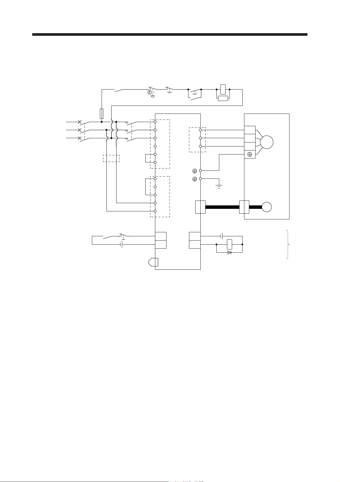
3.1.1 200 V class
(1) Using 3-phase 200 V AC to 240 V AC power supply for MR-J4-10B(-RJ) to MR-J4-350B(-RJ)
ALM
DOCOM
CN3
RA1
L1
L2
L3
P3
P4
P+
L11
L21
N-
D
C
U
V
W
CNP1
CNP3
CNP2
U
V
W
M
CN2
MC
MC
SK
CN3
EM2
DICOM
CN8
MCCB
24 V DC (Note 12)
MC
(Note 7)
(Note 5)
24 V DC (Note 12)
Malfunction (Note 4)
3-phase
200 V AC to
240 V AC
Servo amplifier
(Note 1)(Note 10)
(Note 2)
(Note 13)
Servo motor
Motor
Encoder
(Note 3)
Encoder
cable
(Note 6)
(Note 11)
(Note 11)
(Note 4)
Malfunction
RA1
OFF
ON
Emergency stop switch
(Note 5) Forced stop 2
(Note 9)
Short-circuit connector
(Packed with the servo amplifier)
(Note 8)
Main circuit power supply
Note 1. Between P3 and P4 is connected by default. When using the power factor improving DC reactor, remove the short bar
between P3 and P4. Refer to section 11.11 for details. Additionally, a power factor improving DC reactor and power factor
improvin
g
AC reactor cannot be used simultaneousl
y
.
2.
A
lwa
y
s connect between P+ and D terminals
(
factor
y
-wired
)
. When usin
g
the re
g
enerative option, refer to section 11.2.
3. For the encoder cable, use of the option cable is recommended. For selecting cables, refer to "Servo Motor Instruction
Manual
(
Vol. 3
)
".
4. If ALM (Malfunction) output is disabled with the parameter, configure up the power supply circuit which switches off the
ma
g
netic contactor after detection of alarm occurrence on the controller side.
5. This dia
g
ram shows sink I/O interface. For source I/O interface, refer to section 3.8.3.
6. For connectin
g
servo motor power wires, refer to "Servo Motor Instruction Manual
(
Vol. 3
)
".
7. Use a magnetic contactor with an operation delay time (interval between current being applied to the coil until closure of
contacts) of 80 ms or less. Depending on the main circuit voltage and operation pattern, bus voltage decreases, and that
may cause the forced stop deceleration to shift to the dynamic brake deceleration. When dynamic brake deceleration is not
required, slow the time to turn off the ma
g
netic contactor.
8. Configure a circuit to turn off EM2 when the main circuit power is turned off to prevent an unexpected restart of the servo
amplifier.
9. When not usin
g
the STO function, attach the short-circuit connector came with a servo amplifier.
10. When wires used for L11 and L21 are thinner than wires used for L1, L2, and L3, use a molded-case circuit breaker. (Refer
to section 11.10.
)
11. Connectin
g
a servo motor of the wron
g
axis to U, V, W, or CN2 of the servo amplifier ma
y
cause a malfunction.
12. The illustration of the 24 V DC power supply is divided between input signal and output signal for convenience. However,
the
y
can be confi
g
ured b
y
one.
13. Do not
g
round L11 and L21.
3. SIGNALS AND WIRING
3 - 5
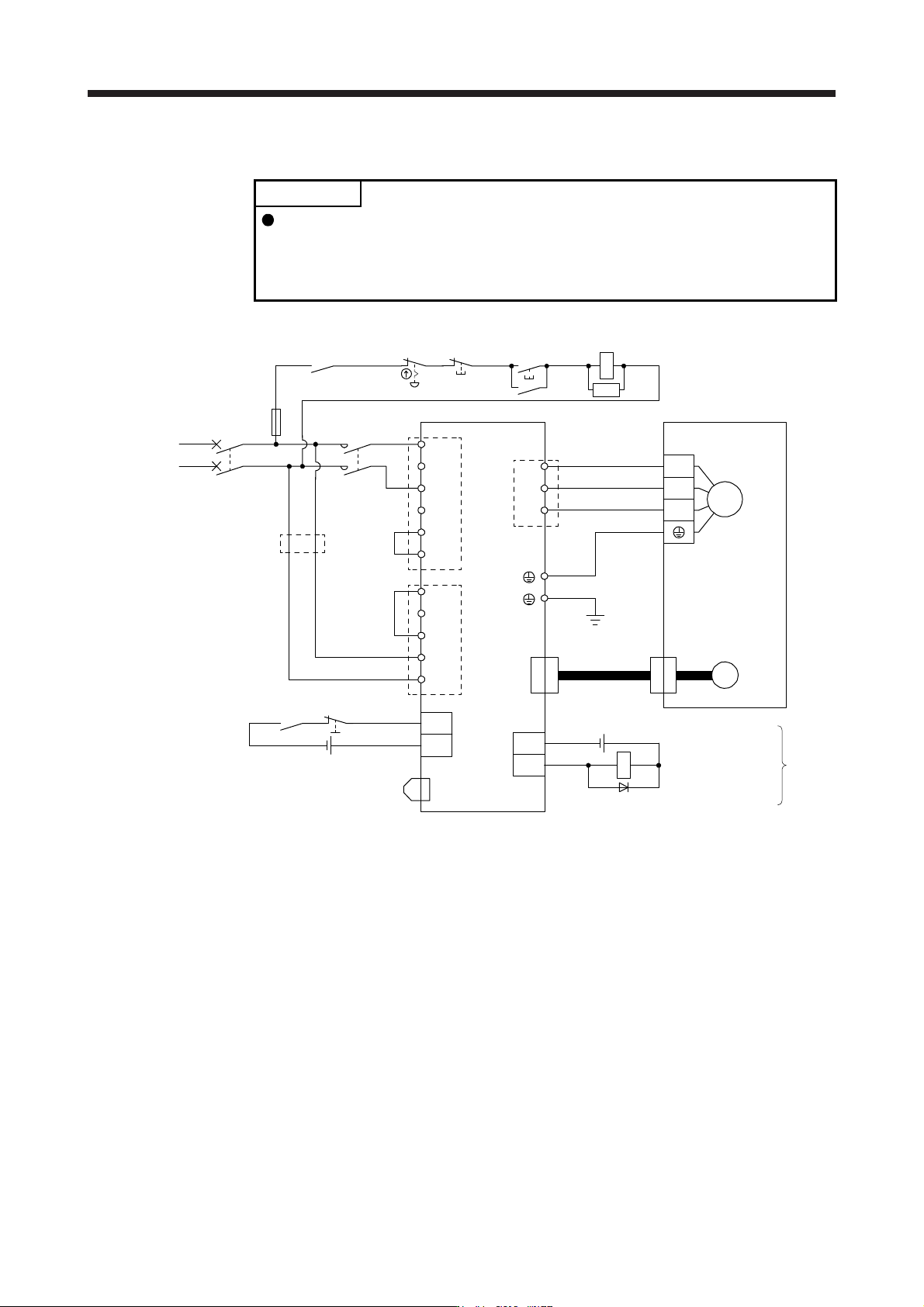
(2) Using 1-phase 200 V AC to 240 V AC power supply for MR-J4-10B(-RJ) to MR-J4-200B(-RJ)
POINT
Connect the 1-phase 200 V AC to 240 V AC power supply to L1 and L3. One of
the connecting destinations is different from MR-J3 Series Servo Amplifier's.
When using MR-J4 as a replacement for MR-J3, be careful not to connect the
power to L2.
L1
L2
L3
P3
P4
P+
L11
L21
N-
D
C
U
V
W
CNP1
CNP3
CNP2
U
V
W
M
CN2
MC
MC
SK
CN8
MCCB
ALM
DOCOM
CN3
RA1
CN3
EM2
DICOM
MC
(Note 7)
(Note 5)
24 V DC (Note 12)
Malfunction (Note 4)
1-phase
200 V AC to
240 V AC
Servo amplifier
(Note 1)
(Note 10)
(Note 2)
(Note 13)
Servo motor
Motor
Encoder
(Note 3)
Encoder
cable
(Note 6)
(Note 4)
Malfunction
RA1
OFF
ON
Emergency stop switch
(Note 5) Forced stop 2
(Note 9)
Short-circuit connector
(Packed with the servo amplifier)
(Note 8)
Main circuit power supply
(Note 11)
(Note 11)
24 V DC (Note 12)
Note 1. Between P3 and P4 is connected by default. When using the power factor improving DC reactor, remove the short bar
between P3 and P4. Refer to section 11.11 for details. Additionally, a power factor improving DC reactor and power factor
improvin
g
AC reactor cannot be used simultaneousl
y
.
2.
A
lwa
y
s connect between P+ and D terminals
(
factor
y
-wired
)
. When usin
g
the re
g
enerative option, refer to section 11.2.
3. For the encoder cable, use of the option cable is recommended. For selecting cables, refer to "Servo Motor Instruction
Manual
(
Vol. 3
)
".
4. If ALM (Malfunction) output is disabled with the parameter, configure up the power supply circuit which switches off the
magnetic contactor after detection of alarm occurrence on the controller side.
5. This dia
g
ram shows sink I/O interface. For source I/O interface, refer to section 3.8.3.
6. For connectin
g
servo motor power wires, refer to "Servo Motor Instruction Manual
(
Vol. 3
)
".
7. Use a magnetic contactor with an operation delay time (interval between current being applied to the coil until closure of
contacts) of 80 ms or less. Depending on the main circuit voltage and operation pattern, bus voltage decreases, and that
may cause the forced stop deceleration to shift to the dynamic brake deceleration. When dynamic brake deceleration is not
required, slow the time to turn off the magnetic contactor.
8. Configure a circuit to turn off EM2 when the main circuit power is turned off to prevent an unexpected restart of the servo
amplifier.
9. When not using the STO function, attach the short-circuit connector came with a servo amplifier.
10. When wires used for L11 and L21 are thinner than wires used for L1, and L3, use a molded-case circuit breaker. (Refer to
section 11.10.
)
11. Connecting a servo motor of the wrong axis to U, V, W, or CN2 of the servo amplifier may cause a malfunction.
12. The illustration of the 24 V DC power supply is divided between input signal and output signal for convenience. However,
the
y
can be confi
g
ured b
y
one.
13. Do not ground L11 and L21.