sh030106u.pdf - 第91页
3. SIG NALS A ND WIRI NG 3 - 14 3.1.3 100 V c lass ALM DOCOM CN3 RA1 L1 L2 P+ L11 L21 N- D C U V W CNP1 CNP3 CNP2 U V W M CN2 MC MC SK CN3 EM2 DICOM CN8 MCCB 24 V DC (Note 12) MC (Note 7) (Note 5) 24 V DC (Note 12) Malfu…

3. SIGNALS AND WIRING
3 - 13
Note 1. Between P3 and P4 is connected by default. When using the power factor improving DC reactor, remove the short bar
between P3 and P4. Refer to section 11.11 for details. Additionally, a power factor improving DC reactor and power factor
improvin
g
AC reactor cannot be used simultaneousl
y
.
2. When usin
g
the re
g
enerative option, refer to section 11.2.
3. For the encoder cable, use of the option cable is recommended. For selecting cables, refer to "Servo Motor Instruction Manual
(
Vol. 3
)
".
4. If ALM (Malfunction) output is disabled with the parameter, configure up the power supply circuit which switches off the
ma
g
netic contactor after detection of alarm occurrence on the controller side.
5. This diagram shows sink I/O interface. For source I/O interface, refer to section 3.8.3 in MR-J4-_B(-RJ) Servo Amplifier
Instruction Manual.
6. For connectin
g
servo motor power wires, refer to "Servo Motor Instruction Manual
(
Vol. 3
)
".
7. Use a magnetic contactor with an operation delay time (interval between current being applied to the coil until closure of
contacts) of 80 ms or less. Depending on the main circuit voltage and operation pattern, bus voltage decreases, and that may
cause the forced stop deceleration to shift to the dynamic brake deceleration. When dynamic brake deceleration is not
required, slow the time to turn off the ma
g
netic contactor.
8. Configure a circuit to turn off EM2 when the main circuit power is turned off to prevent an unexpected restart of the servo
amplifier.
9. When not usin
g
the STO function, attach the short-circuit connector came with a servo amplifier.
10. When wires used for L11 and L21 are thinner than wires used for L1, L2, and L3, use a molded-case circuit breaker. (Refer to
section 11.10.
)
11. Connectin
g
a servo motor for different axis to U, V, W, or CN2 of the servo amplifier ma
y
cause a malfunction.
12. Stepdown transformer is required for coil volta
g
e of ma
g
netic contactor more than 200 V class servo amplifiers.
13. For the servo motor with a coolin
g
fan.
14. For the coolin
g
fan power suppl
y
, refer to "Servo Motor Instruction Manual
(
Vol. 3
)
".
15. The illustration of the 24 V DC power supply is divided between input signal and output signal for convenience. However, they
can be confi
g
ured b
y
one.
16. Use an external dynamic brake for this servo amplifier. Failure to do so will cause an accident because the servo motor does
not stop immediately but coasts at an alarm occurrence for which the servo motor does not decelerate to stop. Ensure the
safety in the entire equipment. For alarms for which the servo motor does not decelerate to stop, refer to chapter 8. For wiring
of the external d
y
namic brake, refer to section 11.17.
17. The external dynamic brake cannot be used for compliance with SEMI-F47 standard. Do not assign DB (Dynamic brake
interlock) in [Pr. PD07] to [Pr. PD09]. Failure to do so will cause the servo amplifier to become servo-off when an
instantaneous power failure occurs.
18. Do not
g
round L11 and L21.
3. SIGNALS AND WIRING
3 - 14
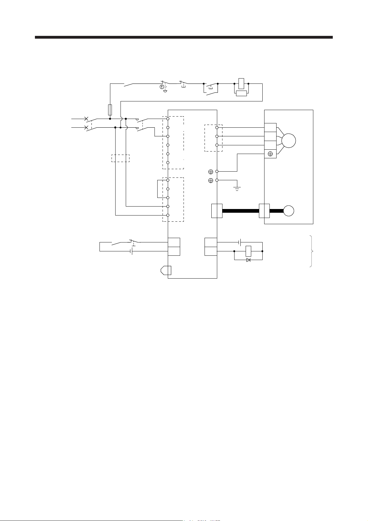
3.1.3 100 V class
ALM
DOCOM
CN3
RA1
L1
L2
P+
L11
L21
N-
D
C
U
V
W
CNP1
CNP3
CNP2
U
V
W
M
CN2
MC
MC
SK
CN3
EM2
DICOM
CN8
MCCB
24 V DC (Note 12)
MC
(Note 7)
(Note 5)
24 V DC (Note 12)
Malfunction (Note 4)
1-phase
100 V AC to
120 V AC
Servo amplifier
(Note 1)(Note 10)
(Note 2)
(Note 13)
Servo motor
Motor
Encoder
(Note 3)
Encoder
cable
(Note 6)
(Note 11)
(Note 11)
(Note 4)
Malfunction
RA1
OFF
ON
Emergency stop switch
(Note 5) Forced stop 2
(Note 9)
Short-circuit connector
(Packed with the servo amplifier)
(Note 8)
Main circuit power supply
Unassigned
Unassigned
Unassigned
Note 1. The power factor improvin
g
DC reactor cannot be used.
2.
A
lwa
y
s connect between P+ and D terminals
(
factor
y
-wired
)
. When usin
g
the re
g
enerative option, refer to section 11.2.
3. For the encoder cable, use of the option cable is recommended. For selecting cables, refer to "Servo Motor Instruction
Manual
(
Vol. 3
)
".
4. If ALM (Malfunction) output is disabled with the parameter, configure up the power supply circuit which switches off the
ma
g
netic contactor after detection of alarm occurrence on the controller side.
5. This dia
g
ram shows sink I/O interface. For source I/O interface, refer to section 3.8.3.
6. For connectin
g
servo motor power wires, refer to "Servo Motor Instruction Manual
(
Vol. 3
)
".
7. Use a magnetic contactor with an operation delay time (interval between current being applied to the coil until closure of
contacts) of 80 ms or less. Depending on the main circuit voltage and operation pattern, bus voltage decreases, and that
may cause the forced stop deceleration to shift to the dynamic brake deceleration. When dynamic brake deceleration is not
required, slow the time to turn off the ma
g
netic contactor.
8. Configure a circuit to turn off EM2 when the main circuit power is turned off to prevent an unexpected restart of the servo
amplifier.
9. When not usin
g
the STO function, attach the short-circuit connector came with a servo amplifier.
10. When wires used for L11 and L21 are thinner than wires used for L1 and L2, use a molded-case circuit breaker. (Refer to
section 11.10.
)
11. Connectin
g
a servo motor of the wron
g
axis to U, V, W, or CN2 of the servo amplifier ma
y
cause a malfunction.
12. The illustration of the 24 V DC power supply is divided between input signal and output signal for convenience. However,
the
y
can be confi
g
ured b
y
one.
13. Do not
g
round L11 and L21.
3. SIGNALS AND WIRING
3 - 15
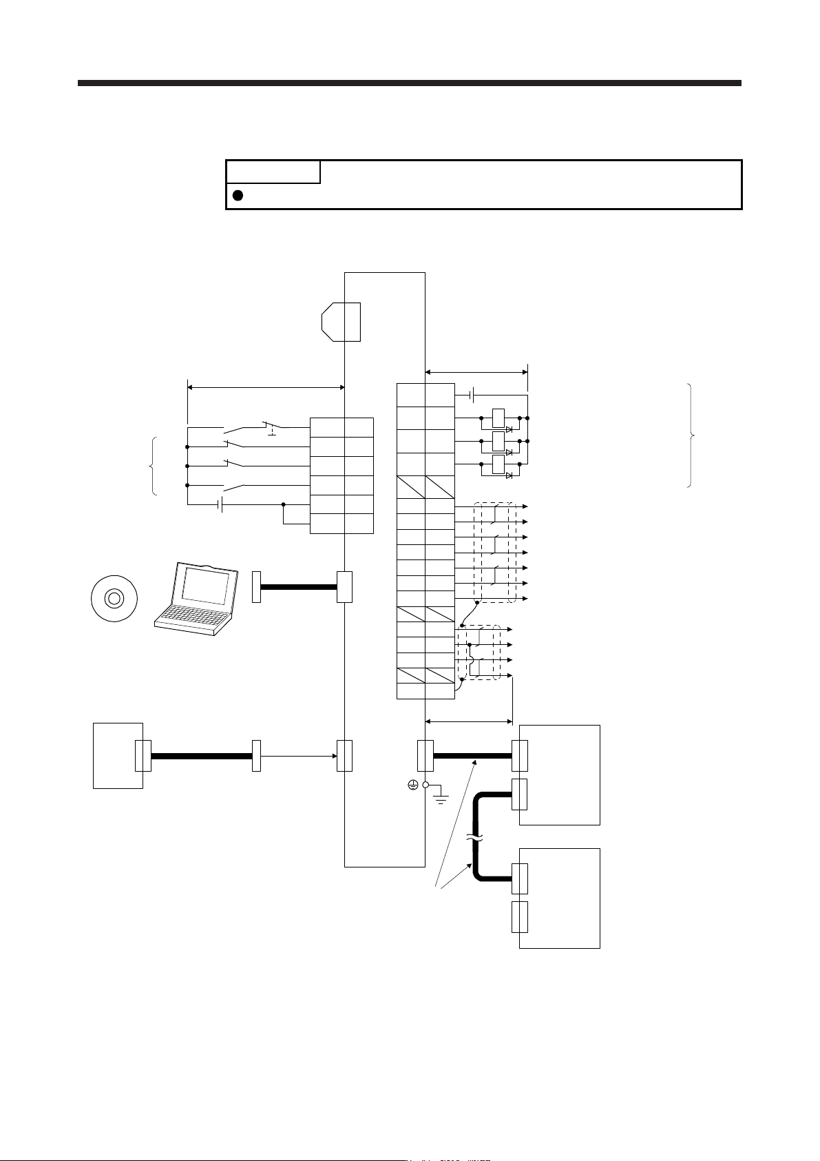
3.2 I/O signal connection example
POINT
EM2 has the same function as EM1 in the torque control mode.
3.2.1 For sink I/O interface
20EM2
2
19
12
DI1
DI3
DI2
(Note 12)
(Note 2)
Servo amplifier
CN3
(Note 12)
(Note 14)
FLS
RLS
DOG
(Note 13)
Encoder A-phase pulse
(differential line driver)
Encoder B-phase pulse
(differential line driver)
Encoder Z-phase pulse
(differential line driver)
CN3
(Note 17)
Electromagnetic brake interlock
13 MBR
9 INP
15 ALM
6LA
16 LAR
7LB
17 LBR
8LZ
18 LZR
Malfunction (Note 11)
In-position
11 LG Control common
RA1
RA2
RA3
DOCOM
DICOM
3
10
5
DICOM
(Note 15)
Main circuit power supply
Personal
computer
CN5
(Note 5)
MR Configurator2
+
USB cable
MR-J3USBCBL3M
(option)
(Note 10) 24 V DC
Analog monitor 1
Analog monitor 2
MO1
LG
MO2
4
1
14
SDPlate
2 m or less
CN8
(Note 16)
Short-circuit connector
(Packed with the servo amplifier)
10 m or less
10 m or less
Servo amplifier
(Note 3, 4)
Forced stop 2
(Note 6)
SSCNET III cable
(option)
Servo system
controller
CN1A
CN1B
(Note 7)
(Note 1)
(Note 9)
Cap
CN1A
CN1B
The last servo amplifier (Note 8)
CN1BCN1A
(Note 6)
SSCNET III cable
(option)
(Note 7)
24 V DC (Note 10)
DC ± 10 V
DC ± 10 V