sh030106u.pdf - 第93页
3. SIG NALS A ND WIRI NG 3 - 16 Note 1. To prev ent an elect ric shock, always connect the prote ct ive earth (PE) terminal (m arked ) of the serv o amplifier to the protectiv e earth ( PE ) of th e cab inet. 2. Connect …
3. SIGNALS AND WIRING
3 - 15
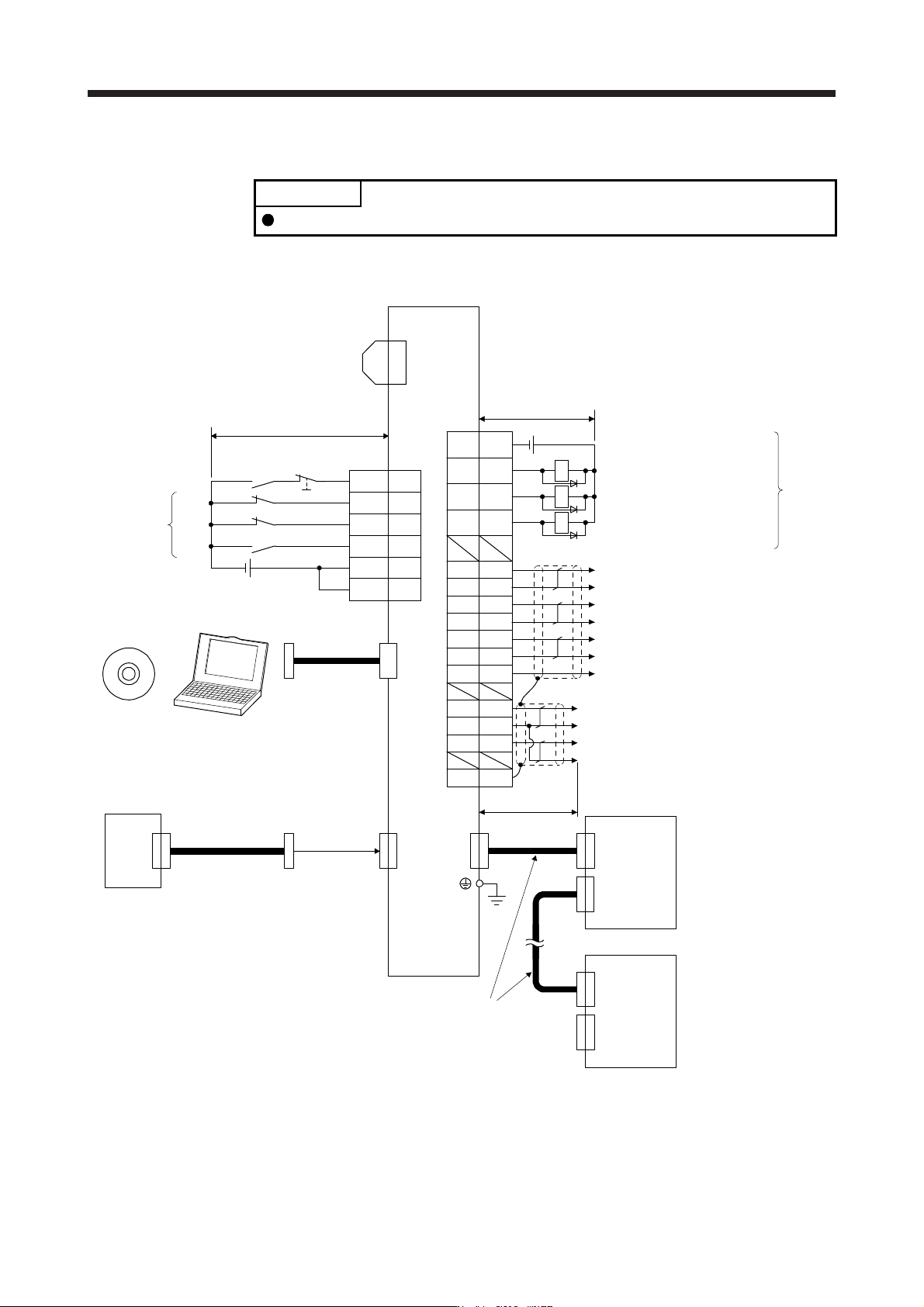
3.2 I/O signal connection example
POINT
EM2 has the same function as EM1 in the torque control mode.
3.2.1 For sink I/O interface
20EM2
2
19
12
DI1
DI3
DI2
(Note 12)
(Note 2)
Servo amplifier
CN3
(Note 12)
(Note 14)
FLS
RLS
DOG
(Note 13)
Encoder A-phase pulse
(differential line driver)
Encoder B-phase pulse
(differential line driver)
Encoder Z-phase pulse
(differential line driver)
CN3
(Note 17)
Electromagnetic brake interlock
13 MBR
9 INP
15 ALM
6LA
16 LAR
7LB
17 LBR
8LZ
18 LZR
Malfunction (Note 11)
In-position
11 LG Control common
RA1
RA2
RA3
DOCOM
DICOM
3
10
5
DICOM
(Note 15)
Main circuit power supply
Personal
computer
CN5
(Note 5)
MR Configurator2
+
USB cable
MR-J3USBCBL3M
(option)
(Note 10) 24 V DC
Analog monitor 1
Analog monitor 2
MO1
LG
MO2
4
1
14
SDPlate
2 m or less
CN8
(Note 16)
Short-circuit connector
(Packed with the servo amplifier)
10 m or less
10 m or less
Servo amplifier
(Note 3, 4)
Forced stop 2
(Note 6)
SSCNET III cable
(option)
Servo system
controller
CN1A
CN1B
(Note 7)
(Note 1)
(Note 9)
Cap
CN1A
CN1B
The last servo amplifier (Note 8)
CN1BCN1A
(Note 6)
SSCNET III cable
(option)
(Note 7)
24 V DC (Note 10)
DC ± 10 V
DC ± 10 V
3. SIGNALS AND WIRING
3 - 16
Note 1. To prevent an electric shock, always connect the protective earth (PE) terminal (marked ) of the servo amplifier to the
protective earth
(
PE
)
of the cabinet.
2. Connect the diode in the correct direction. If it is connected reversely, the servo amplifier will malfunction and will not output
si
g
nals, disablin
g
EM2
(
Forced stop 2
)
and other protective circuits.
3. If the controller does not have forced stop function, alwa
y
s install the forced stop 2 switch
(
normall
y
closed contact
)
.
4. When startin
g
operation, alwa
y
s turn on EM2
(
Forced stop 2
)
.
(
Normall
y
closed contact
)
5. Use SW1DNC-MRC2-
_
.
(
Refer to section 11.7.
)
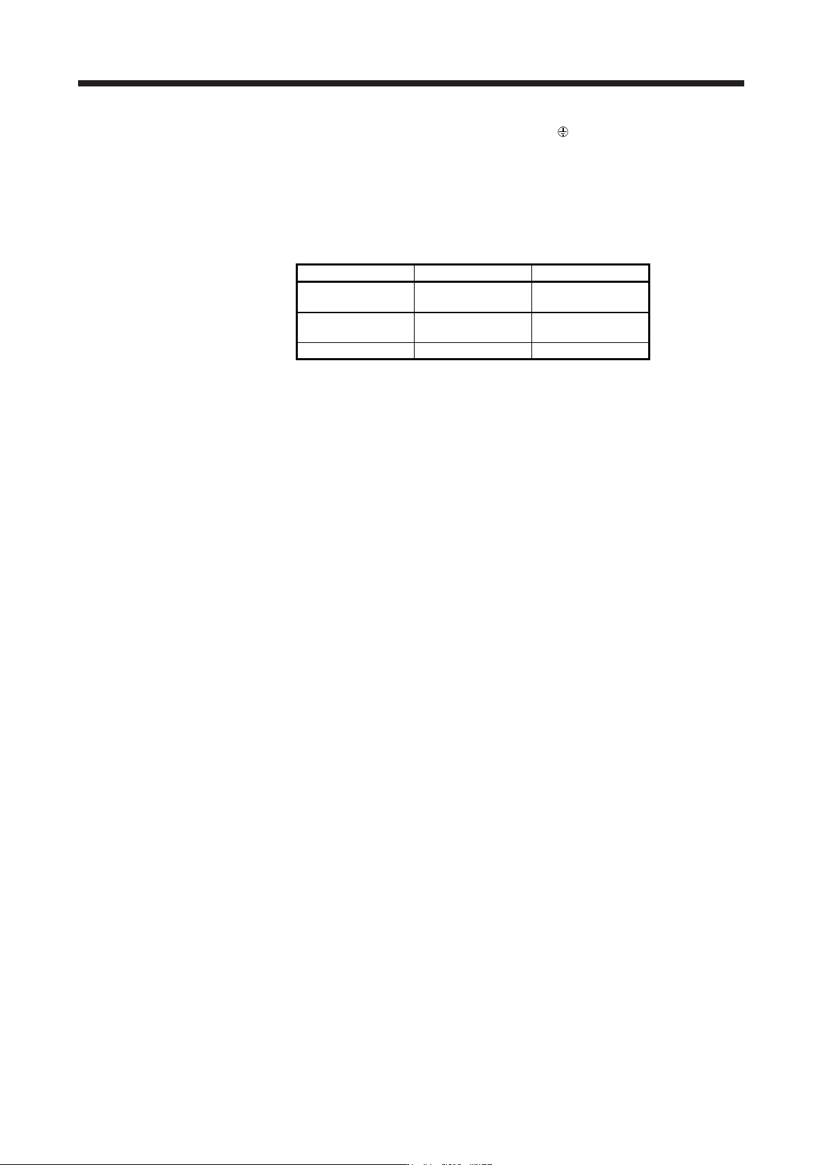
6. Use SSCNET III cables listed in the followin
g
table.
Cable Cable model Cable length
Standard cord inside
cabinet
MR-J3BUS_M 0.15 m to 3 m
Standard cable
outside cabinet
MR-J3BUS_M-A 5 m to 20 m
Long-distance cable MR-J3BUS_M-B 30 m to 50 m
7. The wirin
g
after the second servo amplifier is omitted.
8. Up to 64 axes of servo amplifiers can be connected. The number of connectable axes depends on the controller you use.
Refer to section 4.3.1 for settin
g
of axis selection.
9. Make sure to cap the unused CN1B connector.
10. Supply 24 V DC ± 10% for interfaces from outside. Set the total current capacity to 300 mA. 300 mA is the value applicable
when all I/O signals are used. The current capacity can be decreased by reducing the number of I/O points. Refer to section
3.8.2 (1) that gives the current value necessary for the interface. The illustration of the 24 V DC power supply is divided
between input si
g
nal and output si
g
nal for convenience. However, the
y
can be confi
g
ured b
y
one.
11.
A
LM
(
Malfunction
)
turns on in normal alarm-free condition.
(
Normall
y
closed contact
)
12. The pins with the same si
g
nal name are connected in the servo amplifier.
13. You can chan
g
e devices of these pins with [Pr. PD07], [Pr. PD08], and [Pr. PD09].
14. Devices can be assigned for these signals with controller setting. For devices that can be assigned, refer to the controller
instruction manual. The following devices can be assigned for R_MTCPU, Q17_DSCPU, RD77MS_ and QD77MS_.
FLS: Upper stroke limit
RLS: Lower stroke limit
DOG: Proximit
y
do
g
15. Configure a circuit to turn off EM2 when the main circuit power is turned off to prevent an unexpected restart of the servo
amplifier.
16. When not usin
g
the STO function, attach the short-circuit connector came with a servo amplifier.
17. When you use a linear servo motor or direct drive motor, use MBR (Electromagnetic brake interlock) for an external brake
mechanism.
3. SIGNALS AND WIRING
3 - 17
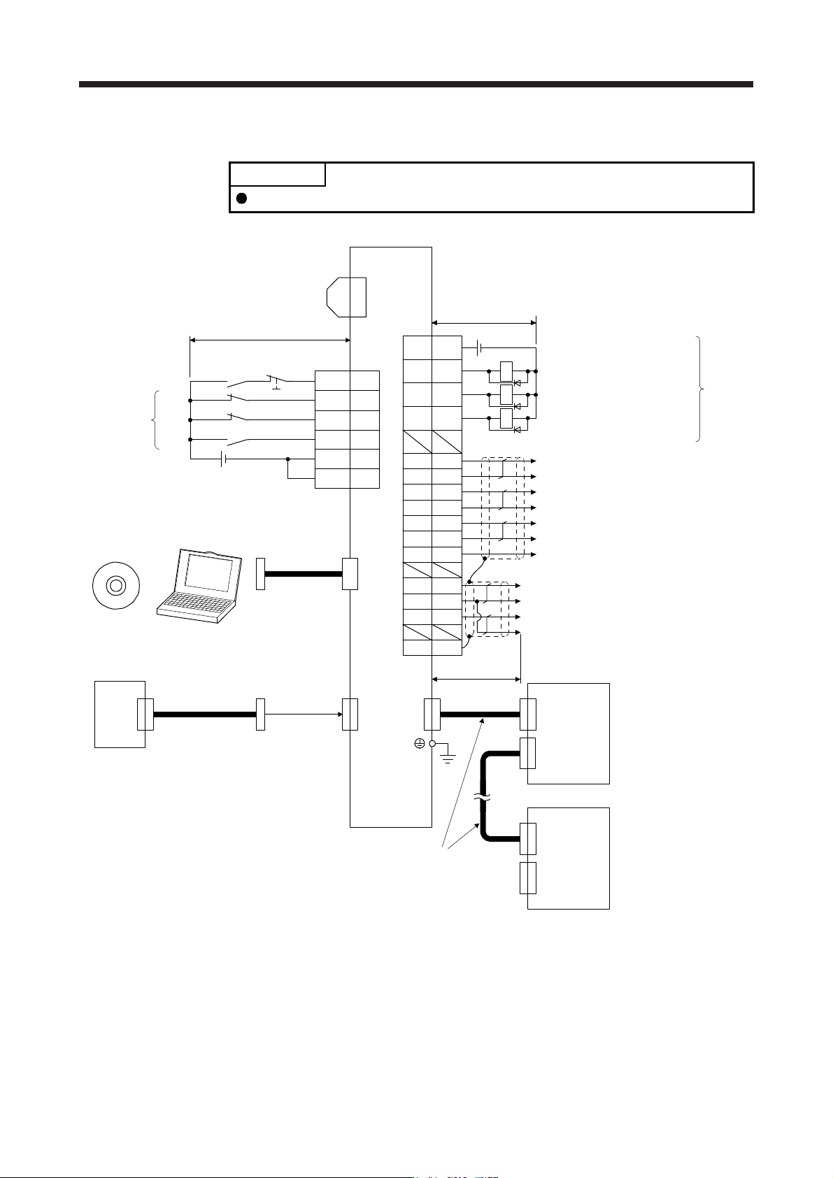
3.2.2 For source I/O interface
POINT
For notes, refer to section 3.2.1.
10
20EM2
2
19
12
DI1
DI3
DI2
3
DOCOM
9 INP
15 ALM
6LA
16 LAR
7LB
17 LBR
8LZ
18 LZR
11 LG
RA1
RA2
5DICOM
DICOM
MO1
LG
MO2
4
1
14
SD
Plate
CN8
RA3
CN1A
CN1B
(Note 12)
Servo amplifier
CN3
(Note 12)
(Note 14)
FLS
RLS
DOG
(Note 13)
Encoder A-phase pulse
(differential line driver)
Encoder B-phase pulse
(differential line driver)
Encoder Z-phase pulse
(differential line driver)
CN3
(Note 2)
Electromagnetic brake interlock
Malfunction (Note 11)
In-position
Control common
(Note 15)
Main circuit power supply
Personal
computer
CN5
(Note 5)
MR Configurator2
+
USB cable
MR-J3USBCBL3M
(option)
(Note 10) 24 V DC
Analog monitor 1
Analog monitor 2
2 m or less
(Note 16)
Short-circuit connector
(Packed with the servo
amplifier) 10 m or less
10 m or less
Servo amplifier
(Note 3, 4)
Forced stop 2
(Note 6)
SSCNET III cable
(option)
Servo system
controller
(Note 7)
(Note 1)
(Note 9)
Cap
CN1A
CN1B
The last servo amplifier (Note 8)
CN1BCN1A
(Note 6)
SSCNET III cable
(option)
(Note 7)
24 V DC (Note 10)
13 MBR