sh030106u.pdf - 第95页
3. SIG NALS A ND WIRI NG 3 - 18 3.3 Explan atio n of po wer sup ply syst em 3.3.1 Sign al ex planat ions POINT For the lay out of co nnect or and ter minal b lock, refer to chapte r 9 DIMEN SIONS. When usi ng the MR-J4-_…
3. SIGNALS AND WIRING
3 - 17
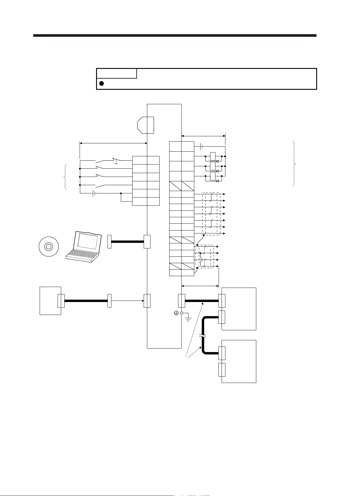
3.2.2 For source I/O interface
POINT
For notes, refer to section 3.2.1.
10
20EM2
2
19
12
DI1
DI3
DI2
3
DOCOM
9 INP
15 ALM
6LA
16 LAR
7LB
17 LBR
8LZ
18 LZR
11 LG
RA1
RA2
5DICOM
DICOM
MO1
LG
MO2
4
1
14
SD
Plate
CN8
RA3
CN1A
CN1B
(Note 12)
Servo amplifier
CN3
(Note 12)
(Note 14)
FLS
RLS
DOG
(Note 13)
Encoder A-phase pulse
(differential line driver)
Encoder B-phase pulse
(differential line driver)
Encoder Z-phase pulse
(differential line driver)
CN3
(Note 2)
Electromagnetic brake interlock
Malfunction (Note 11)
In-position
Control common
(Note 15)
Main circuit power supply
Personal
computer
CN5
(Note 5)
MR Configurator2
+
USB cable
MR-J3USBCBL3M
(option)
(Note 10) 24 V DC
Analog monitor 1
Analog monitor 2
2 m or less
(Note 16)
Short-circuit connector
(Packed with the servo
amplifier) 10 m or less
10 m or less
Servo amplifier
(Note 3, 4)
Forced stop 2
(Note 6)
SSCNET III cable
(option)
Servo system
controller
(Note 7)
(Note 1)
(Note 9)
Cap
CN1A
CN1B
The last servo amplifier (Note 8)
CN1BCN1A
(Note 6)
SSCNET III cable
(option)
(Note 7)
24 V DC (Note 10)
13 MBR
3. SIGNALS AND WIRING
3 - 18
3.3 Explanation of power supply system
3.3.1 Signal explanations
POINT
For the layout of connector and terminal block, refer to chapter 9 DIMENSIONS.
When using the MR-J4-_B-RJ servo amplifier with the DC power supply input,
refer to app. 15.
Symbol
Connection target
(application)
Description
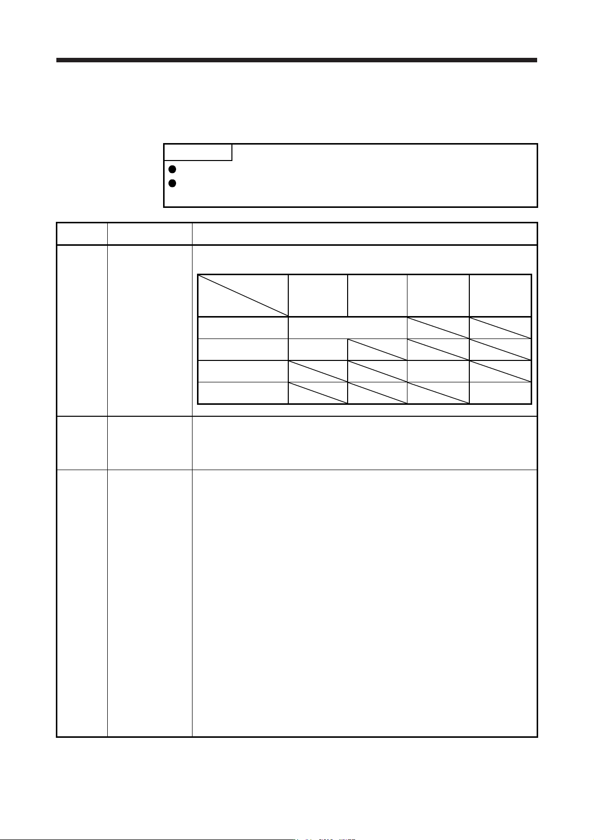
L1/L2/L3
Main circuit power
supply
Supply the following power to L1, L2, and L3. For 1-phase 200 V AC to 240 V AC, connect the
power supply to L1 and L3. Leave L2 open.
Servo amplifier
Power
MR-J4-10B
(-RJ) to
MR-J4-200B
(-RJ)
MR-J4-350B
(-RJ) to
MR-J4-22KB
(-RJ)
MR-J4-60B4
(-RJ) to
MR-J4-22KB4
(-RJ)
MR-J4-10B1 to
MR-J4-40B1
3-phase 200 V AC to
240 V AC, 50 Hz/60 Hz
L1/L2/L3
1-phase 200 V AC to
240 V AC, 50 Hz/60 Hz
L1/L3
3-phase 380 V AC to
480 V AC, 50 Hz/60 Hz
L1/L2/L3
1-phase 100 V AC to
120 V AC, 50 Hz/60 Hz
L1/L2
P3/P4
Power factor
improving DC reactor
When not using the power factor improving DC reactor, connect P3 and P4. (factory-wired)
When using the power factor improving DC reactor, disconnect P3 and P4, and connect the
power factor improving DC reactor to P3 and P4. Additionally, the power factor improving DC
reactor cannot be used for the 100 V class servo amplifiers.
Refer to section 11.11 for details.
P+/C/D Regenerative option
(1) 200 V class/100 V class
1) MR-J4-500B(-RJ) or less and MR-J4-40B1(-RJ) or less
When using a servo amplifier built-in regenerative resistor, connect P+ and D. (factory-
wired)
When using a regenerative option, disconnect P+ and D, and connect the regenerative
option to P+ and C.
2) MR-J4-700B(-RJ) to MR-J4-22KB(-RJ)
MR-J4-700B(-RJ) to MR-J4-22KB(-RJ) do not have D.
When using a servo amplifier built-in regenerative resistor, connect P+ and C. (factory-
wired)
When using a regenerative option, disconnect wires of P+ and C for the built-in
regenerative resistor. And then connect wires of the regenerative option to P+ and C.
(2) 400 V class
1) MR-J4-350B4(-RJ) or less
When using a servo amplifier built-in regenerative resistor, connect P+ and D. (factory-
wired)
When using a regenerative option, disconnect P+ and D, and connect the regenerative
option to P+ and C.
2) MR-J4-500B4(-RJ) to MR-J4-22KB4(-RJ)
MR-J4-500B4(-RJ) to MR-J4-22KB4(-RJ) do not have D.
When using a servo amplifier built-in regenerative resistor, connect P+ and C. (factory-
wired)
When using a regenerative option, disconnect wires of P+ and C for the built-in
regenerative resistor. And then connect wires of the regenerative option to P+ and C.
Refer to section 11.2 for details.
3. SIGNALS AND WIRING
3 - 19
Symbol
Connection target
(application)
Description
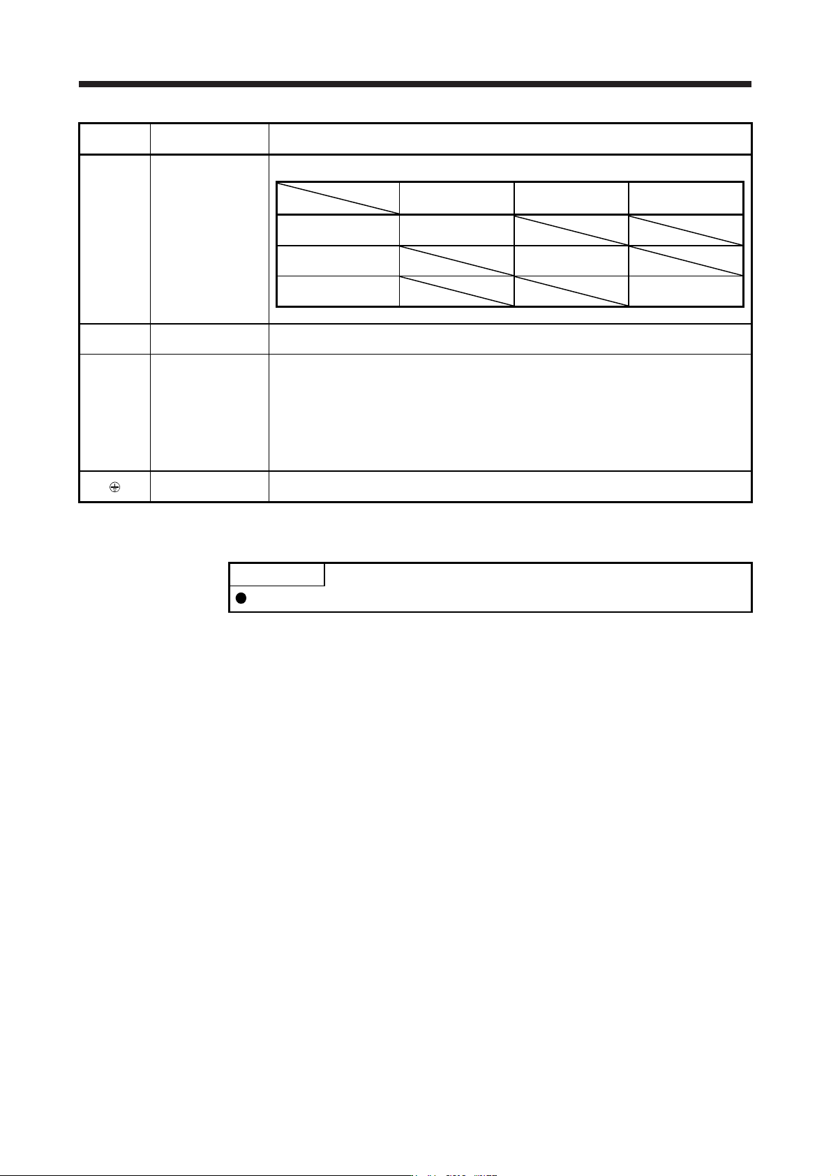
L11/L21
Control circuit power
supply
Supply the following power to L11 and L21.
Servo amplifier
Power
MR-J4-10B(-RJ) to
MR-J4-22KB(-RJ)
MR-J4-60B4(-RJ) to
MR-J4-22KB4(-RJ)
MR-J4-10B1 to
MR-J4-40B1
1-phase 200 V AC to
240 V AC, 50 Hz/60 Hz
L11/L21
1-phase 380 V AC to
480 V AC, 50 Hz/60 Hz
L11/L21
1-phase 100 V AC to
120 V AC, 50 Hz/60 Hz
L11/L21
U/V/W
Servo motor power
input
Connect the servo amplifier power output (U/V/W) to the servo motor power input (U/V/W)
directly. Do not let a magnetic contactor, etc. intervene. Otherwise, it may cause a malfunction.
N-
Power regeneration
converter
Power regeneration
common converter
Brake unit
Multifunction
regeneration
converter
This terminal is used for a power regeneration converter, power regeneration common
converter, brake unit, and multifunction regeneration converter.
For details, refer to sections 11.3 through 11.5 and 11.19.
Protective earth (PE)
Connect it to the grounding terminal of the servo motor and to the protective earth (PE) of the
cabinet for grounding.
3.3.2 Power-on sequence
POINT
The output signal, etc. may be unstable at power-on.
(1) Power-on procedure
1) Always wire the power supply as shown in above section 3.1 using the magnetic contactor with
the main circuit power supply (L1/L2/L3). Configure up an external sequence to switch off the
magnetic contactor as soon as an alarm occurs.
2) Switch on the control circuit power supply (L11/L21) simultaneously with the main circuit power
supply or before switching on the main circuit power supply. If the control circuit power supply is
turned on with the main circuit power supply off, and then the servo-on command is transmitted,
[AL. E9 Main circuit off warning] will occur. Turning on the main circuit power supply stops the
warning and starts the normal operation.
3) The servo amplifier receives the servo-on command within 3 s to 4 s after the main circuit power
supply is switched on.
(Refer to (2) in this section.)