sh030106u.pdf - 第98页
3. SIG NALS A ND WIRI NG 3 - 21 (b) MR-J4- 200B(-R J)/MR-J 4-350B(-RJ ) CNP2 CNP1 CNP3 MR-J4-200B(-RJ) Servo amplifier CNP3 CNP1 CNP2 MR-J4-350B(-RJ) Servo amplifier Table 3.2 Connec tor and appl icable w ire Connector R…
3. SIGNALS AND WIRING
3 - 20
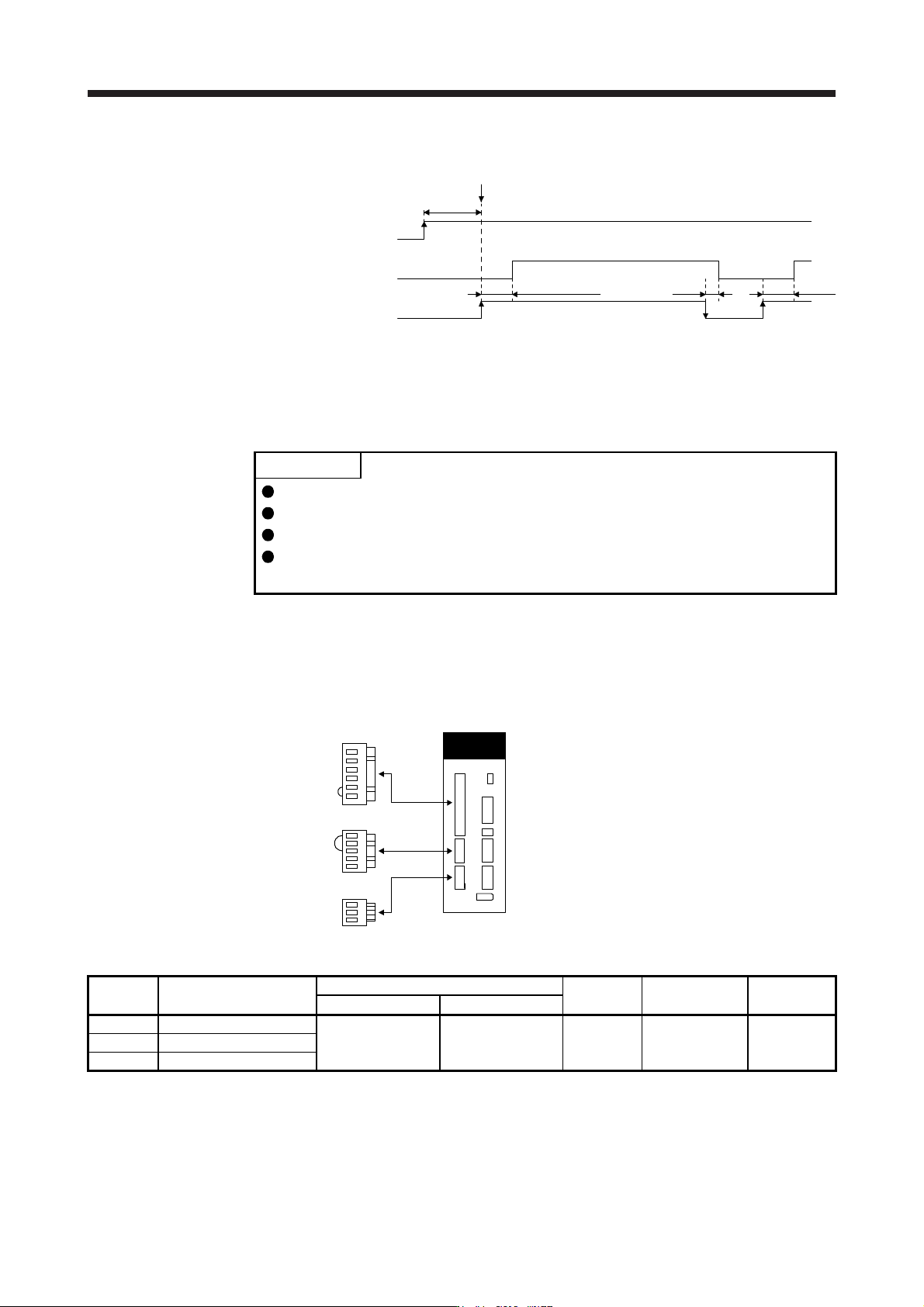
(2) Timing chart
(Note 1)
(3 s to 4 s)
95 ms (Note 2) 10 ms 95 ms
Servo-on command accepted
Main circuit
Control circuit
Base circuit
Servo-on command
(from controller)
power supply
ON
OFF
ON
OFF
ON
OFF
Note 1. This ran
g
e will be "5 s to 6 s" for the linear servo s
y
stem and full
y
closed loop s
y
stem.
2. The time will be lon
g
er durin
g
the ma
g
netic pole detection of a linear servo motor and direct drive motor.
3.3.3 Wiring CNP1, CNP2, and CNP3
POINT
For the wire sizes used for wiring, refer to section 11.9.
When wiring, remove the power connectors from the servo amplifier.
Insert only one wire or ferrule to each wire insertion hole.
MR-J4-500B(-RJ) or more and MR-J4-500B4(-RJ) or more do not have these
connectors.
Use the servo amplifier power connector for wiring CNP1, CNP2, and CNP3.
(1) Connector
(a) MR-J4-10B(-RJ) to MR-J4-100B(-RJ)
CNP2
CNP1
CNP3
Servo amplifier
Table 3.1 Connector and applicable wire
Connector Receptacle assembly
Applicable wire
Stripped
length [mm]
Open tool Manufacturer
Size Insulator OD
CNP1 06JFAT-SAXGDK-H7.5
AWG 18 to 14 3.9 mm or shorter 9
J-FAT-OT (N)
or
J-FAT-OT
JST
CNP2 05JFAT-SAXGDK-H5.0
CNP3 03JFAT-SAXGDK-H7.5
3. SIGNALS AND WIRING
3 - 21
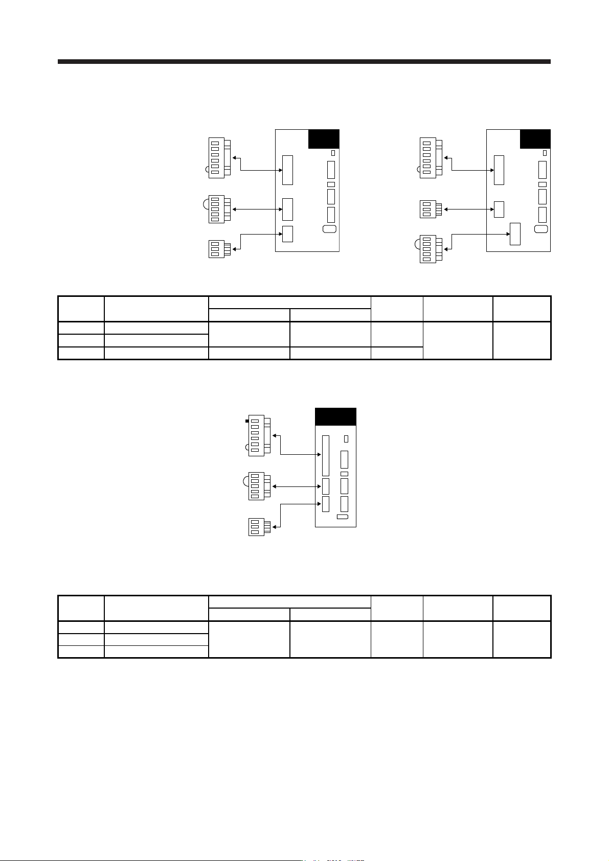
(b) MR-J4-200B(-RJ)/MR-J4-350B(-RJ)
CNP2
CNP1
CNP3
MR-J4-200B(-RJ)
Servo amplifier
CNP3
CNP1
CNP2
MR-J4-350B(-RJ)
Servo amplifier
Table 3.2 Connector and applicable wire
Connector Receptacle assembly
Applicable wire
Stripped
length [mm]
Open tool Manufacturer
Size Insulator OD
CNP1 06JFAT-SAXGFK-XL
AWG 16 to 10 4.7 mm or shorter 11.5
J-FAT-OT-EXL JST
CNP3 03JFAT-SAXGFK-XL
CNP2 05JFAT-SAXGDK-H5.0 AWG 18 to 14 3.9 mm or shorter 9
(c) MR-J4-60B4(-RJ) to MR-J4-350B4(-RJ)
CNP2
CNP1
CNP3
Servo amplifier
(Note)
Note.
A
pin for preventin
g
improper connection is inserted to N- of CNP1 connector.
Table 3.3 Connector and applicable wire
Connector Receptacle assembly
Applicable wire
Stripped
length [mm]
Open tool Manufacturer
Size Insulator OD
CNP1 06JFAT-SAXGDK-HT10.5
AWG 16 to 14 3.9 mm or shorter 10 J-FAT-OT-XL JST
CNP2 05JFAT-SAXGDK-HT7.5
CNP3 03JFAT-SAXGDK-HT10.5
3. SIGNALS AND WIRING
3 - 22
(d) MR-J4-10B1(-RJ) to MR-J4-40B1(-RJ)
CNP2
CNP1
CNP3
Servo amplifier
Table 3.4 Connector and applicable wire
Connector Receptacle assembly
Applicable wire
Stripped
length [mm]
Open tool Manufacturer
Size Insulator OD
CNP1 06JFAT-SAXGDK-H7.5
AWG 18 to 14 3.9 mm or shorter 9
J-FAT-OT (N)
or
J-FAT-OT
JST
CNP2 05JFAT-SAXGDK-H5.0
CNP3 03JFAT-SAXGDK-H7.5
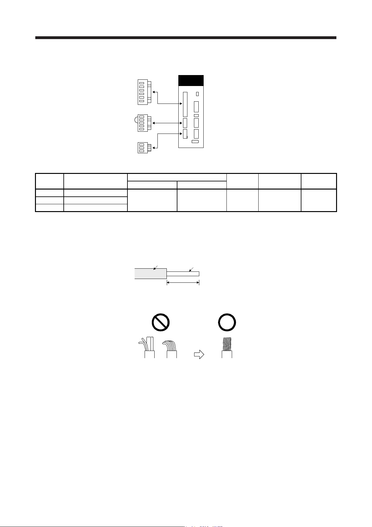
(2) Cable connection procedure
(a) Fabrication on cable insulator
Refer to table 3.1 to 3.4 for stripped length of cable insulator. The appropriate stripped length of
cables depends on their type, etc. Set the length considering their status.
Insulator
Core
Stripped length
Twist strands lightly and straighten them as follows.
Loose and bent strands Twist and straighten
the strands.