00194086-01.pdf - 第104页
4 Setting up t he placement system Us er Manual SIPLACE CS 4.3 Adjusting the com ponent trolley to an other PCB transport height Software V ersion SR.408.xx03/2006 US E dition 104 Æ Inser t the two A llen keys (8 mm) int…
User Manual SIPLACE CS 4 Setting up the placement system
Software Version SR.408.xx 03/2006 US Edition 4.3 Adjusting the component trolley to another PCB transport height
103
4.3 Adjusting the component trolley to another PCB
transport height
4.3.1 Tools
Allen keys, set up to 8 mm
4.3.2 Safety instructions
WARNING DANGER OF CRUSHING
Remove all the feeders from the component table bed before you adjust the table height of the
component trolley. Act with considerable care during the conversion process because the table
bed is very heavy. 4
4
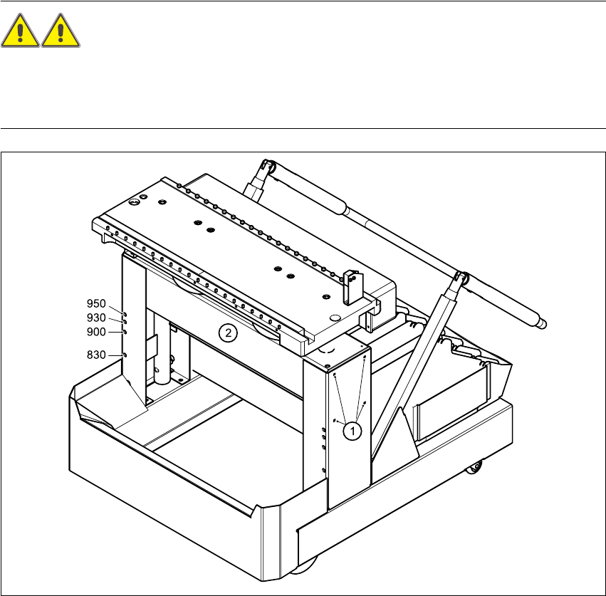
Fig. 4.3 - 1 Adjusting the component trolley to another PCB transport height
(1) Clamping screws, 4 per side
(2) Holes in the cross-beam for adjusting the table height to 830, 900, 930 and 950 mm

4 Setting up the placement system User Manual SIPLACE CS
4.3 Adjusting the component trolley to another PCB transport height Software Version SR.408.xx03/2006 US Edition
104
Æ Insert the two Allen keys (8 mm) into the correct holes for the current PCB transport height (see
Fig. 4.3 - 1
).
Æ Loosen the four clamping screws on both sides of the component trolley (see point 1 in Fig.
4.3 - 1
).
Æ Ask two people to help you raise and lower the table bed: they should hold the table bed while
you remove the two Allen keys.
Æ Raise or lower the table bed to the desired PCB transport height.
Æ Push the two Allen keys (8 mm) into the hole for the new transport height.
Æ Turn the Allen keys so that the cross-beam (item 2 in Fig. 4.3 - 1) is seated on the edge of the
keys. You can then fix the cross-beam in place and easily pull out the Allen keys.
Æ Fix the cross-beam on both sides with the four clamping screws (item 1 in Fig. 4.3 - 1).
Æ Now turn the Allen keys slightly and remove.

User Manual SIPLACE CS 5 Tasks on the machine
Software Version SR.408.xx 03/2006 US Edition 5.1 Personnel profile
105
5 Tasks on the machine
This chapter contains a number of subjects that are intended to help you during your daily work
on a SIPLACE line.
For example, you are provided with preventative measures that you can take to minimize the
down time on the machine to obtain the highest possible level of efficiency for the SIPLACE line
during production.
In addition, the tasks of the operator and of the line engineer are described in an operator and line
engineer profile, respectively, in this chapter.
5.1 Personnel profile
5.1.1 Operator
5.1.1.1 Tasks of the operator
The operators should generally have attended the SIPLACE operation training course or have
been instructed by trained personnel.
The operating personnel are to be assigned the following tasks:
– Checking the assignment of components to the feeders
→ In addition, a set-up check is to be carried out several times a day, preferably at the start
of a shift, to make sure that the correct components are set up.
– Supplying the feeder modules with sufficient components
– Promptly refilling the components and splicing the tapes
– Checking to make sure that the components are in their correct pick-up positions (see Fig.
5.6 - 1
)
– Checking the flow of material to the PCBs on the input and output conveyor
– Checking the set-up quality
– Random sampling of the PCBs before they enter the soldering furnace.
– Observing the ESD regulations
– Preventing errors (see Section 5.6
, page 117)
– Observing the fault displays and messages at the station and passing the information on to
the line engineer if necessary
– Carrying out the preventive maintenance work specified in the Preventive Maintenance Man-
ual