00194086-01.pdf - 第78页
3 Technical data User Manual SIPLACE CS 3.7 Gantries Software Version SR.408.xx03/2006 US Edition 78 3.7 Gantries 3.7.1 Position of the gantries 3 Fig. 3.7 - 1 Position of the gantries (1) Gantry 1 (2) Gantry 2 The gantr…

User Manual SIPLACE CS 3 Technical data
Software Version SR.408.xx 03/2006 US Edition 3.6 Component barcode reader
77
Track allocation
Four-digit barcode strips are attached to the lateral safety screens for the purposes of track allo-
cation. The first digit is used to identify the component table (1 or 2), while the remaining three
digits specify the track number. There are also return barcodes at both ends of the barcode strip.
The barcode strips are numbered consecutively in intervals of two (1, 3, 5, 7...) and each repre-
sents 2 tracks (barcode 1 = track 1 and 2).
Components
Data can be read from the component reels to compare the stock of components against the
quantity specified in the set-up file (refill check), for example.
An audible signal is given when each dataset has been read successfully.
PLEASE NOTE 3
The component barcode reader option must be configured on the SIPLACE C Pro computer.
Barcodes that start with the number 1 or 2 and are 5 digits long are interpreted as track bar-
codes. All other barcodes that do not start with number 1 or 2 are regarded as component bar-
codes. 3
3.6.2 Technical data
3
Connection Station computer
Data entry Via barcode reader or keyboard
Number of characters Up to 40
Not permissible Barcodes starting with a 1 or 2 and less than 5 characters long
Number of barcodes Up to 6 per component
Filter for suppressing data Up to 1 per barcode
Preset code types Code 39 (standard or ASCII)
Code 2 of 5, interleaved and normal,
Code 128, UPC/EAN/JAN codes
(others available upon request)
3 Technical data User Manual SIPLACE CS
3.7 Gantries Software Version SR.408.xx03/2006 US Edition
78
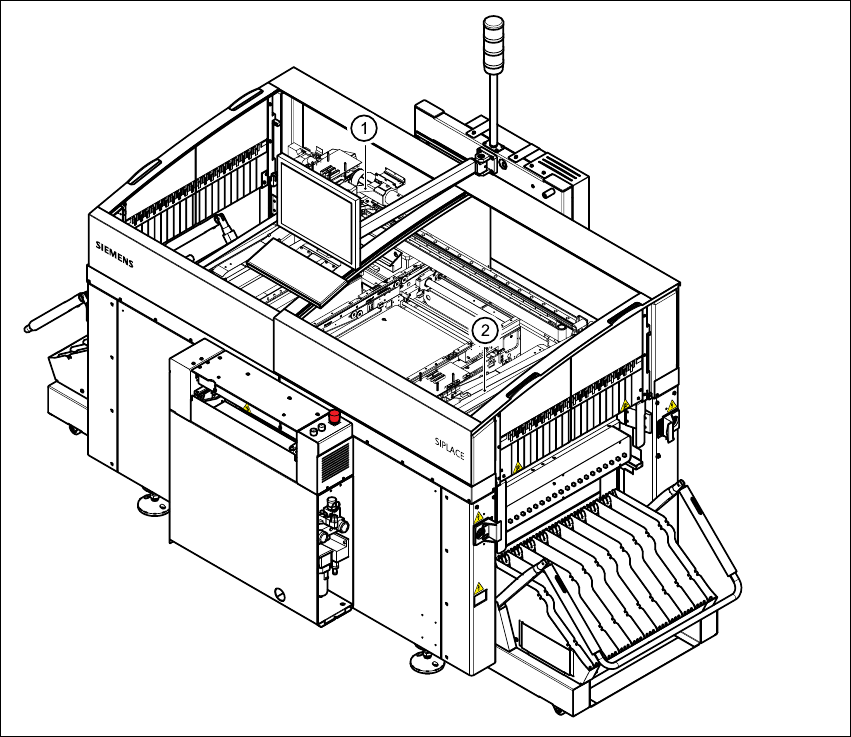
3.7 Gantries
3.7.1 Position of the gantries
3
Fig. 3.7 - 1 Position of the gantries
(1) Gantry 1
(2) Gantry 2
The gantry system consists of two functional groups
–X-axis and
–Y-axis
User Manual SIPLACE CS 3 Technical data
Software Version SR.408.xx 03/2006 US Edition 3.7 Gantries
79
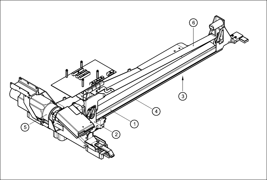
3.7.2 Structure of the X axis
3
Fig. 3.7 - 2 Structure of the X-axis
The X-axis essentially consists of the following main modules:
– Gantry arm (1)
– Head mount (2)
– X-axis measuring system (3)
– X-axis guide system (4)
– X-axis three-phase AC servomotor (5)
– Toothed belt (6)
The head mount holds the following components
– Sub-gantry camera (camera for the PCB vision module)
– Head board
– Measuring head for the X-axis measuring system
– Collect&Place head