00194086-01.pdf - 第88页
3 Technical data User Manual SIPLACE CS 3.10 Nozzle changer for the 6-segment C ollect&Place head Software Version SR.408.xx03/2006 US Edition 88 Fig. 3.10 - 1 Nozz le changer for the 6-segment Collect&P lace hea…

User Manual SIPLACE CS 3 Technical data
Software Version SR.408.xx 03/2006 US Edition 3.10 Nozzle changer for the 6-segment Collect&Place head
87
3.10 Nozzle changer for the 6-segment Collect&Place
head
3.10.1 Overview
The placement system is supplied as standard with two Collect&Place heads. As an option, a
nozzle changer can be installed for each Collect&Place head. This enables the nozzle configura-
tion to be changed quickly, thus allowing the Collect&Place head to be quickly adapted to the
needs of the placement process.
The nozzle changer consists of at least one, and up to five magazines, each with twelve nozzle
garages (see Fig. 3.10 - 1
). The magazines are seated on a common support. Each magazine is
centered using two parallel pins and fixed in place with a spring hook.
3.10.2 Technical data
3
Nozzle changer for the 6-segment Collect&Place head
Dimensions (length x width x height) 673 mm x 74 mm x 75 mm
Number of nozzle garages Min. 6 / max. 30
Nozzle types 9 xx
Time required to open and close the locking plate < 200 ms
Capacity of the reject bin Approx. 50 nozzles
Pneumatic system Compressed air line 0.53 MPa (5.3 bar)
3 Technical data User Manual SIPLACE CS
3.10 Nozzle changer for the 6-segment Collect&Place head Software Version SR.408.xx03/2006 US Edition
88
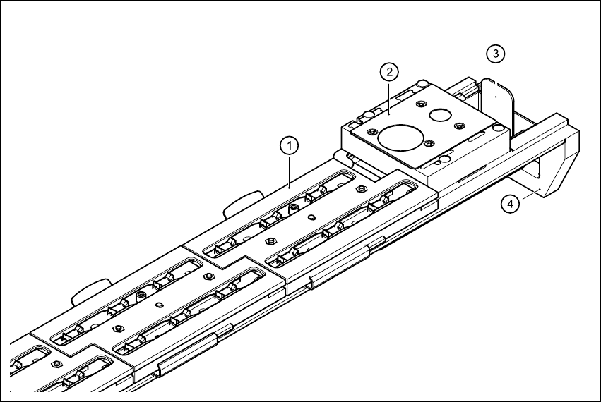
Fig. 3.10 - 1 Nozzle changer for the 6-segment Collect&Place head, overview
(1) Magazine
(2) Nozzle discarding device
(3) Reject bin for discarded nozzles
(4) Nozzle changer, base

User Manual SIPLACE CS 3 Technical data
Software Version SR.408.xx 03/2006 US Edition 3.10 Nozzle changer for the 6-segment Collect&Place head
89
3.10.3 Mode of operation
The nozzles are seated in nozzle garages and are held in place by a movable locking plate. The
locking plate can be moved 6 mm by a pneumatic cylinder. All the nozzles are either clamped or
released, depending on the position of the plate. The default position of the locking plate, i.e. if
there is no nozzle change in progress, is "closed".
There is a positioning fiducial for position detection on each magazine of the nozzle changer. The
magazine locations are identified by numbers 1 to 5 on the nozzle changer. The nozzle garages
in the magazines are numbered consecutively from 1 to 6 (see Fig. 3.10 - 2
).
PLEASE NOTE 3
Special magazines are available upon request (contact SIEMENS A&D for details) and will be
numbered differently. 3
Picking up a nozzle
– The Collect&Place head Z axis moves down.
– The locking plate (item 2 in Fig. 3.10 - 2
) opens and releases the nozzles.
– The nozzle is picked up by the sleeve of the Collect&Place head.
– The Z axis moves up.
Setting down a nozzle
– The locking plate (item 2 in Fig. 3.10 - 2) opens and releases the nozzles.
– The Collect&Place head Z axis moves down and sets the nozzle down.
– The locking plate closes.
– The Collect&Place head Z axis moves up.
Discarding defective nozzles
– The Collect&Place head Z axis moves down 14 mm towards the discarding device (item 2 in
Fig. 3.10 - 1
) and thus moves the defective nozzle into the hole in the discarding device.
– The Z axis moves up again and the nozzle is stripped from the sleeve by spring wires.
– The nozzle drops into the container (item 3 in Fig. 3.10 - 1
).