00194086-01.pdf - 第96页
3 Technical data User Manual SIPLACE CS 3.11 PCB conveyor Software Version SR.408.xx03/2006 US Edition 96 3.1 1.2 T echnica l dat a 3 PCB form at (length x wi dth) 50 mm x 5 0 mm to 508 mm x 460 mm (2" x 2 " to…
User Manual SIPLACE CS 3 Technical data
Software Version SR.408.xx 03/2006 US Edition 3.11 PCB conveyor
95
3.11 PCB conveyor
3.11.1 Structure of the PCB conveyor
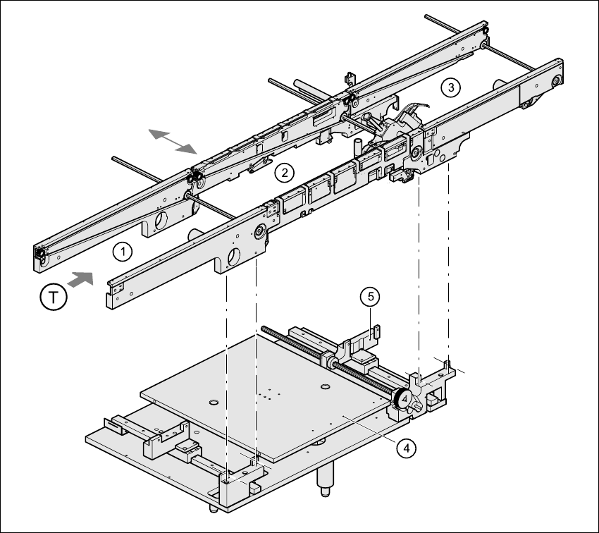
The placement machine is supplied with a PCB conveyor. The left or the right side of the PCB
conveyor can be used as the stationary side, as required.
3
Fig. 3.11 - 1 PCB conveyor
(1) Input conveyor
(2) Center conveyor
(3) Output conveyor
(4) Lifting table
(5) Width adjustment
(T) Direction of PCB transport

3 Technical data User Manual SIPLACE CS
3.11 PCB conveyor Software Version SR.408.xx03/2006 US Edition
96
3.11.2 Technical data
3
PCB format
(length x width)
50 mm x 50 mm to 508 mm x 460 mm
(2" x 2" to 20" x 18")
Long board: length up to 610 mm (24") (available upon
request)
PCB thickness 0.5 mm to 4.5 mm
Max. PCB warpage Up: 4.5 mm - PCB thickness
Down: 0.5 mm + PCB thickness
Clearance on PCB underside 25 mm (standard), 40 mm (option)
PCB transport height 830 mm ± 15 mm (standard)
900 mm ± 15 mm (optional)
930 mm ± 15 mm (optional)
950 mm ± 15 mm (SMEMA: optional)
Fixed conveyor side Right (standard), left (optional)
Type of interface Siemens
SMEMA
Component-free PCB handling edge 3 mm
PCB changeover time 2.5 s
Bad fiducial detection Possible
Automatic width adjustment Possible
User Manual SIPLACE CS 3 Technical data
Software Version SR.408.xx 03/2006 US Edition 3.12 Magnetic pin support
97
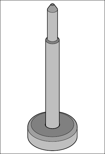
3.12 Magnetic pin support
Item no. 00119680-xx
Wide boards tend to deflect during placement such that, under certain circumstances, the compo-
nents can no longer be placed with the desired accuracy. Highly curved PCBs also affect the
placement accuracy. This problem can be easily rectified by fitting magnetic pin supports on the
lifting table.
3
Fig. 3.12 - 1 Magnetic pin support