5989-5509.pdf - 第10页
Page 10 Find us at www .keysight.com Peak h old Signal wid th A ccuracy for DC mV/volt age/current Single event > 1 ms 2 % + 40 0 for all ranges Repe titive > 25 0 µs 2 % + 1 00 0 for all ranges Duty cycle a nd pu …
Page 9
Find us at www.keysight.com
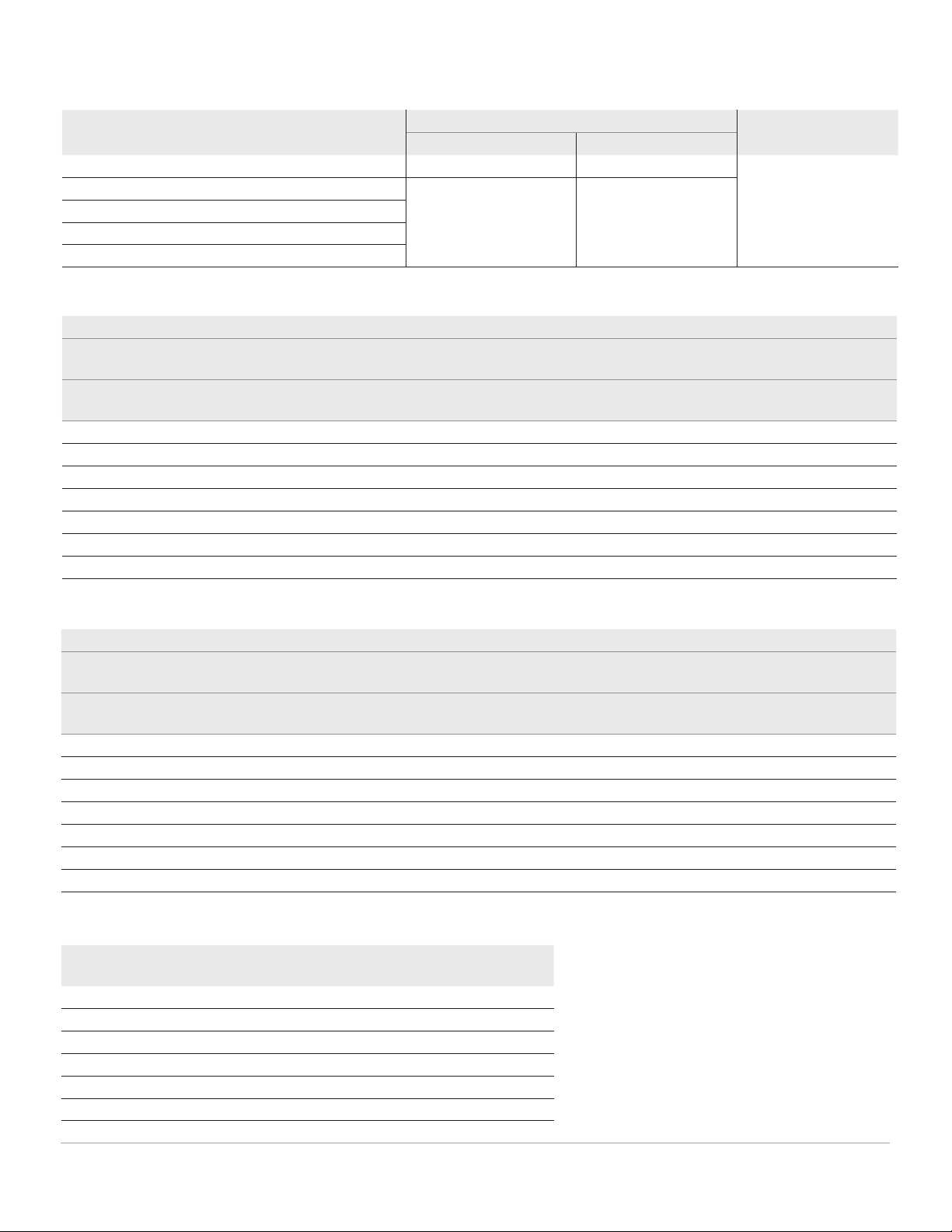
U1251B frequency sensitivity during voltage measurement
Frequency sensitivity and trigger level
Input range
3
Minimum sensitivity
(R.M.S. Sine Wave)
Trigger level for DC coupling
(Maximum input for specified
accuracy = 10 x Range or 1000 V)
20 Hz - 100 kHz >100 kHz ~ 200 kHz < 100 kHz >100 kHz ~ 200 kHz
50.000 mV 10 mV 15 mV 10 mV 15 mV
500.00 mV 25 mV 35 mV 60 mV 70 mV
1000.0 mV 40 mV 50 mV 100 mV 150 mV
5.0000 V 0.25 V 0.5 V 0.5 V / 1.25 V (< 100 Hz) 0.6 V
50.000 V 2.5 V 5 V 5 V 6 V
500.00 V 25 V N/A 50 V N/A
1000.0 V 50 V N/A 300 V N/A
U1252B/U1253B frequency sensitivity during voltage measurement
Frequency sensitivity and trigger level
Input range
3
Minimum sensitivity
(RMS sine wave)
Trigger level for DC coupling
(Maximum input for specified
accuracy = 10 x range or 1000 V)
20 Hz ~ 200 kHz >200 kHz ~ 500 kHz < 100 kHz >100 kHz ~ 500 kHz
50.000 mV 10 mV 25 mV 10 mV 25 mV
500.00 mV 70 mV 150 mV 70 mV 150 mV
1000.0 mV 120 mV 300 mV 120 mV 300 mV
5.0000 V 0.3 V 1.2 V 0.6 V 1.5 V
50.000 V 3 V 5 V 6 V 15 V
500.00 V 30 V < 100 kHz N/A 60 V N/A
1000.0 V 50 V < 100 kHz N/A 120 V N/A
Frequency sensitivity during current measurement
Input range Minimum sensitivity (RMS sine wave)
20 Hz ~ 20 Khz
500.00 µA 100 µA
5000.0 µA 250 µA
50.000 mA 10 mA
440.00 mA 25 mA
5.0000 A 1 A
10.000 A 2.5 A
Frequency specifications
5
Range Resolution Accuracy Min. input frequency
1
U1251B/2B U1253B
99.999 Hz 0.001 Hz 0.02%+3
9
0.02%+3
9
1 Hz
999.99 Hz 0.01 Hz 0.02%+3, <600 kHz 0.02%+3, <600 kHz
9.9999 kHz 0.0001 kHz
99.999 kHz 0.001 kHz
999.99 kHz 0.01 kHz
1. The input signal is lower than the product of 20000000 V
x Hz (product voltage and frequency); overload protection:
1000 V.
2. The multimeter will automatically select the most appropriate
range when making frequency measurements.
3. Maximum input for specified accuracy = 10 x range or 1000
V.
Page 10
Find us at www.keysight.com
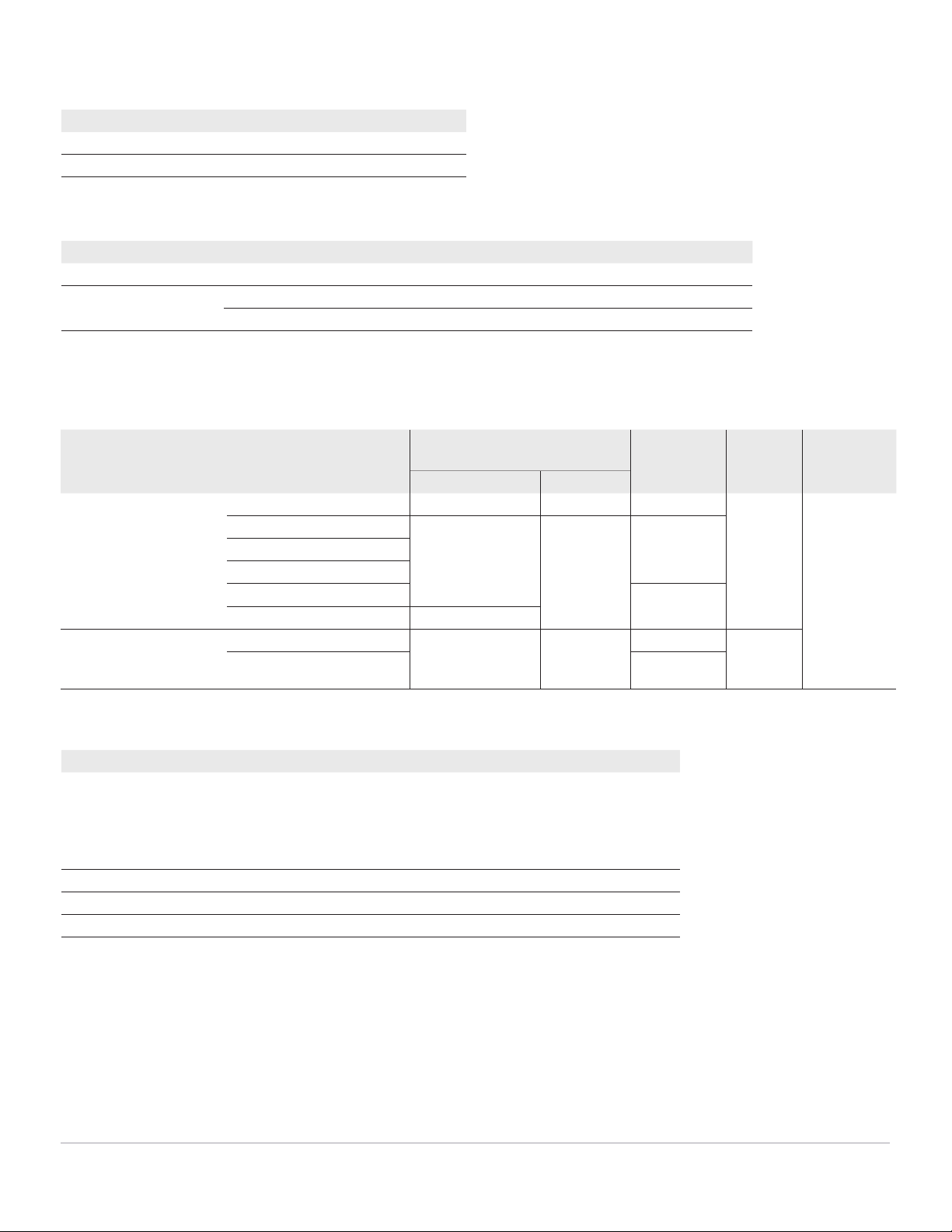
Peak hold
Signal width Accuracy for DC mV/voltage/current
Single event > 1 ms 2% + 400 for all ranges
Repetitive > 250 µs 2% + 1000 for all ranges
Duty cycle and pulse width
1
Function Mode Range Accuracy at full scale
Duty cycle DC Coupling 0.01% ~ 99.99% 0.3% per kHz + 0.3%
Pulse width 500 ms 0.01 ms 0.2% + 3
2000 ms 0.1 ms 0.2% + 3
1. The positive or negative pulse width must be greater than 10 µs, and the duty cycle range should be considered.
The pulse width range is determined by the frequency of the signal.
U1252B/U1253B square wave output
Output
2
Range Resolution Accuracy
Frequency 0.5, 1, 2, 5, 6
6
, 10, 15, 20, 25,
30, 40, 50, 60, 75, 80, 100, 120,
150, 200, 240, 300, 400, 480,
600, 800, 1200, 1600, 2400,
48000 Hz
0.01 Hz 0.005% + 2
Duty cycle
3
0.39% ~ 99.60% 0.390625% 0.4% of full scale
4
Pulse width
4
1/frequency Range/256 0.2 ms + range/256
Amplitude Fixed 0 ~ +2.8 V 0.1 V 0.2 V
U1252B/U1253B frequency counter specifications
Division Range Resolution Accuracy ± (% of reading +
no. of least significant digit)
Sensitivity Min. input
frequency
Maximum
measurement
level
U1252B U1253B
1
(secondary display “-1-“)
99.999 Hz 0.001 Hz 0.02% + 3
1
0.02% + 3
1
300 mV R.M.S. 0.5 Hz < 30 Vpp
999.99 Hz 0.01 Hz 0.002% + 5, <985
kHz
0.002% + 5,
< 985 kHz
100 mV R.M.S.
9.9999 kHz 0.0001 kHz
99.999 kHz 0.001 kHz
999.99 kHz 0.01 kHz 600 mV R.M.S.
9.9999 MHz 0.0001 MHz 0.002% + 5, < 1 MHz
100
(secondary display “-100-“)
9.9999 MHz 0.0001 MHz 0.002% + 5, < 20
MHz
0.002% + 5,
< 20 MHz
600 mV R.M.S. 1 MHz
99.999 MHz 0.001 MHz 600 mV R.M.S.
Page 11
Find us at www.keysight.com
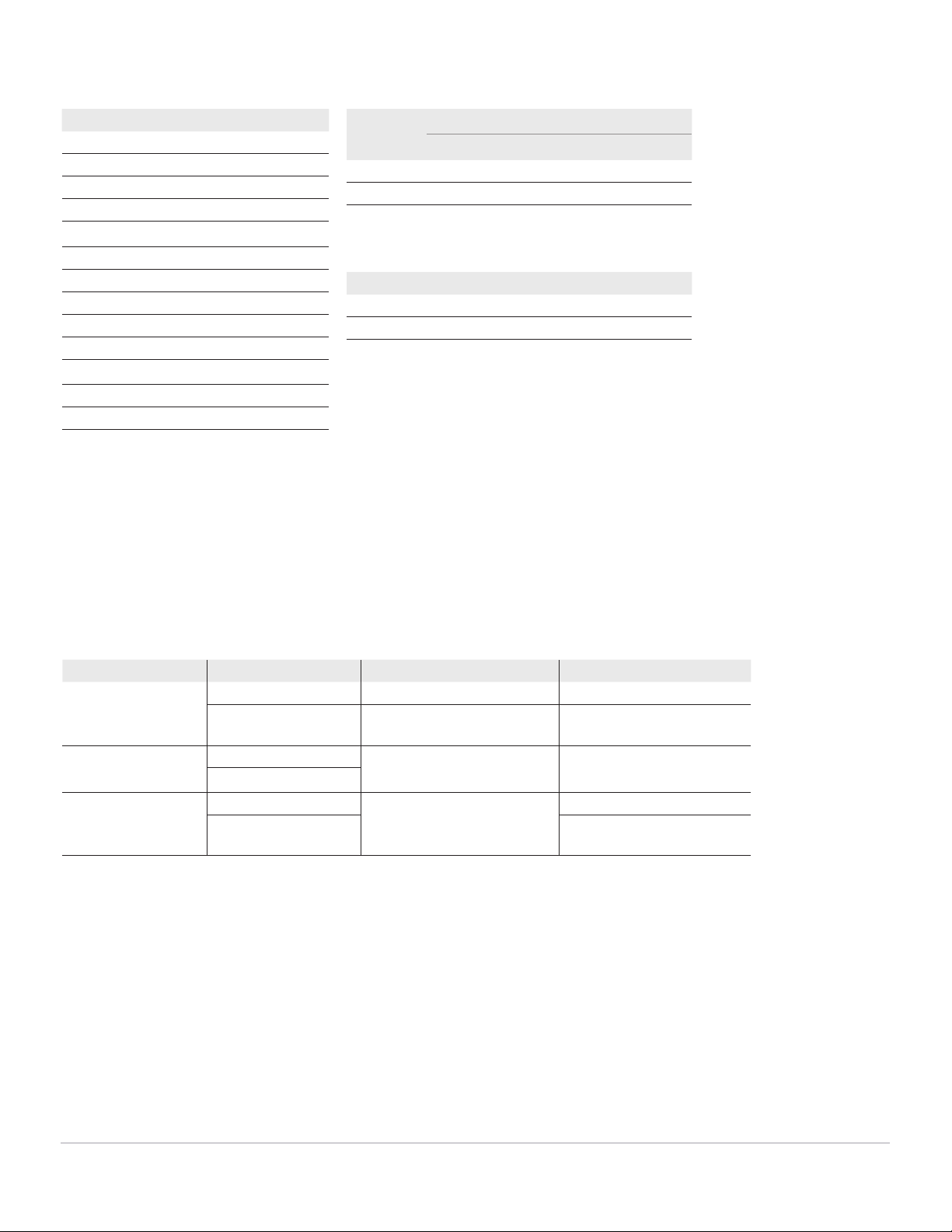
Display rate
Function Times/second
ACV 7
ACV + dB 7
DCV 7
AC + DC V 2
Ω/nS 14
Diode 14
Capacitance 4 (< 100 µF)
DCI 7
ACI 7
AC + DC I 2
Temperature 6
Frequency 1 (>10 Hz)
Duty cycle/pulse width 0.5 (>10 Hz)
Decibel (Db) calculation
dB Base Reference Default reference
1 mΩ (dBm) 1-9999 Ω 50 Ω
1 V (dBV) 1 V 1 V
Manual and interval data logging
Logging type Maximum data points
5
U1251B U1252B U1253B
Manual 100 100 100
Interval 200 200 1000
1. All frequency counters are susceptible to errors. Shielding inputs from external noise pickup is critical to minimize measurement errors. For
non-square wave signals, add 5 counts.
2. Output impedance: 3.5 kΩ maximum.
3. The positive or negative pulse width must be greater than 50 µs for adjustment of the duty cycle or pulse width under different frequencies.
Otherwise, the accuracy and range will be different from the specifications defined.
4. For signal frequencies greater than 1 kHz, an addition of 0.1% per kHz is added to the accuracy.
5. For data logging to PC, maximum number of data points is dependent on available hard disk space.
6. For the U1253B model.
Input impedance
Table A
Function Range U1251B U1252B/U1253B
DC voltage 50 mV to 1000 mV 10 MΩ 10 MΩ
5 V to 1000 V 10 MΩ (nominal), with 10 MΩ in
parallel at dual display
10 MΩ (nominal), with 10 MΩ in
parallel at dual display
AC voltage 50 mV to 1000 mV 10 MΩ in parallel with < 100 pF 10 MΩ in parallel with < 100 pF
5 V to 1000 V
AC + DC voltage 50 mV to 1000 mV N/A 10 MΩ
5 V to 1000 V 10 MΩ (nominal) in parallel with 10
MΩ, < 100 pF