Nordson_EFD_Automated_Dispensing_Systems_Maintenance_Guide - 第27页
27 www.nordsonefd.com info@nordsonefd.com +1-401-431-7000 Sales and service of Nordson EFD dispensing systems are available worldwide. Automated Dispensing Systems Maintenance & Parts Guide Timing Belt and Motor Repl…
Automated Dispensing Systems Maintenance & Parts Guide
26 www.nordsonefd.com info@nordsonefd.com +1-401-431-7000 Sales and service of Nordson EFD dispensing systems are available worldwide.
Replace the ZAxis Timing Belt (E2 / E2V units only)
5
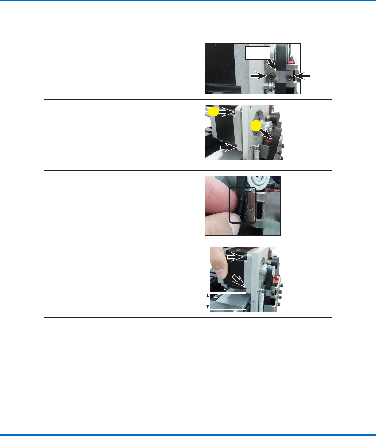
Release the two (2) screws that fasten the
timing belt fixing plate and then remove the
plate.
Timing belt
fixing plate
6
a. Release the four (4) screws that fasten the
motor to the robot. This loosens the timing
belt enough to remove it from the idler and
timing pulleys.
NOTE: The screw only needs to be
loosened, not completely removed.
b. Remove the old timing belt from the idler
and timing pulley.
a
b
7
With the sawtooth sides of the new timing belt
facing one another, loop the belt around the
idler and timing pulleys.
Align the sawtooth pattern of the timing belt so
it matches the pattern on the Zaxis module that
is covered by the timing belt fixing plate.
8
Adjust the motor to the upright position and
tighten the four (4) screws that fasten the motor
to the robot.
NOTE: The tension is not measured for this
belt.
9
Secure the timing belt fixing plate with the two (2) screws removed previously.
Timing Belt and Motor Replacement: ZAxis (continued)
Continued on next page
27www.nordsonefd.com info@nordsonefd.com +1-401-431-7000 Sales and service of Nordson EFD dispensing systems are available worldwide.
Automated Dispensing Systems Maintenance & Parts Guide
Timing Belt and Motor Replacement: ZAxis (continued)
Replace the ZAxis Motor (All Units Except E2 / E2V and R / RV Series)
10
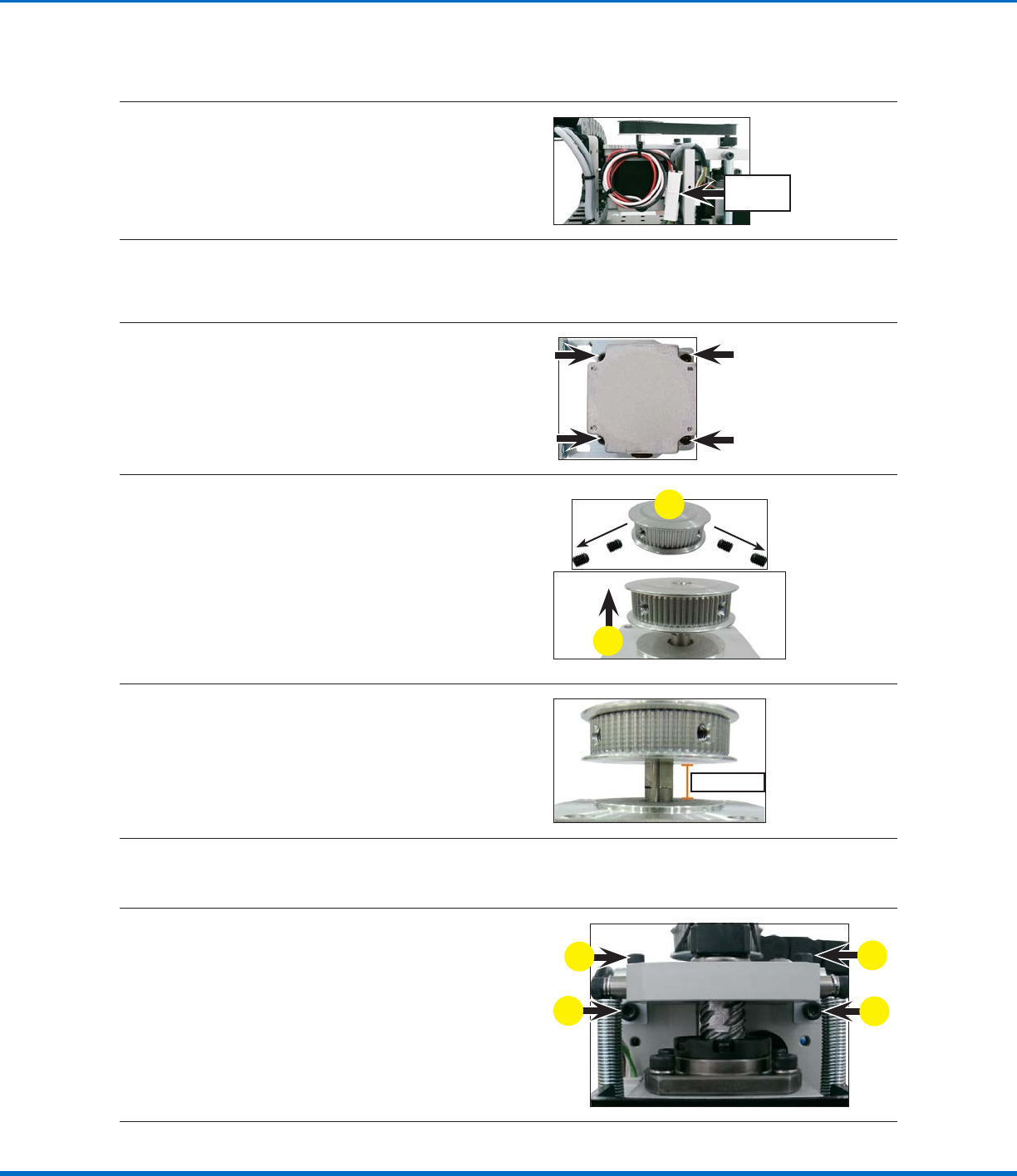
Disconnect the Zaxis motor cable.
Zaxis
motor cable
11
Release the four (4) screws on the motor fixing base.
This loosens the motor enough to remove the timing belt from the timing pulley, at which point the
motor fixing base and timing pulley can be completely removed from the Zaxis module.
12
Release the four (4) screws fastening the Zaxis
motor to the motor fixing base and then place
the isolated motor on the work bench.
13
a. Release the four (4) set screws located
inside the threaded holes of the timing
pulley.
NOTE: Two set screws are used in each
hole: one screw for initial contact with the
shaft and a second screw to secure the
position.
b. Lift the timing pulley off the Zaxis motor
shaft.
b
a
14
a. Assemble the timing pulley onto the new
Zaxis motor shaft; position the timing pulley
such that the two (2) set screw holes align
with the two flat surfaces of the motor shaft.
b. Ensure that the distance from the base of
the timing pulley to the top of the motor is
10 mm (0.4").
10 mm (0.4")
15
Secure the new Zaxis motor and the timing pulley to the motor fixing base with the four (4) screws
removed previously.
16
Secure the motor fixing base to the Zaxis
module as follows:
a. Tighten the two (2) horizontal screws to
secure the timing belt.
b. Tighten the two (2) vertical screws to secure
the motor fixing base to the Zaxis module.
NOTE: The tension is not measured for this
belt.
b
a
b
a
Continued on next page
Automated Dispensing Systems Maintenance & Parts Guide
28 www.nordsonefd.com info@nordsonefd.com +1-401-431-7000 Sales and service of Nordson EFD dispensing systems are available worldwide.
Timing Belt and Motor Replacement: ZAxis (continued)
Replace the ZAxis Motor (E2 / E2V Units Only)
17
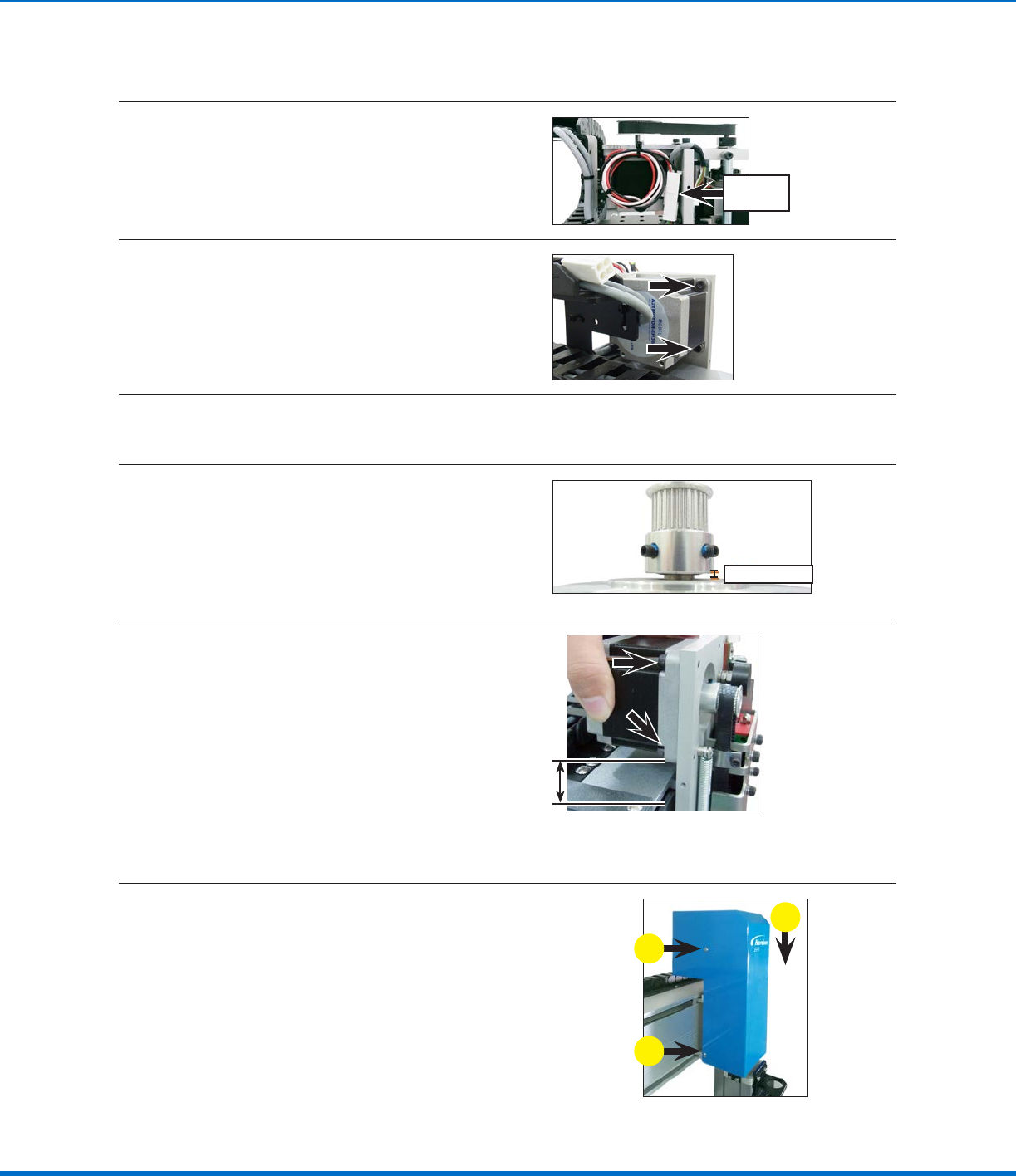
Disconnect the Zaxis motor cable.
Zaxis
motor cable
18
Release the four (4) screws that fasten the
motor to the Zaxis module.
This loosens the motor enough to remove the
timing belt from the timing pulley, at which point
the motor can be completely removed from the
robot.
19
Remove the two (2) set screws on the timing pulley and then pull the timing pulley away from the
motor.
20
a. Assemble the timing pulley onto the shaft of
the new motor; align the timing pulley such
that the two (2) set screws contact the two
flat surfaces of the motor shaft.
b. Ensure that the distance from the base of
the timing pulley to the top of the motor is
3.5 mm (0.14").
3.5 mm (0.14")
21
Adjust the motor to the upright position and
tighten the four (4) screws that fasten the motor
to the Zaxis module.
NOTE: The tension is not measured for this
belt.
Reinstall the ZAxis Cover
22.
a. Reinstall the Zaxis cover.
b. Secure the cover with the screws removed
previously.
b
a
b