Nordson_EFD_Automated_Dispensing_Systems_Maintenance_Guide - 第32页
Automated Dispensing Systems Maintenance & Parts Guide 32 www.nordsonefd.com info@nordsonefd.com +1-401-431-7000 Sales and service of Nordson EFD dispensing systems are available worldwide. Timing Belt and Motor Repl…
31www.nordsonefd.com info@nordsonefd.com +1-401-431-7000 Sales and service of Nordson EFD dispensing systems are available worldwide.
Automated Dispensing Systems Maintenance & Parts Guide
Timing Belt and Motor Replacement: Z and R Axes (continued)
8
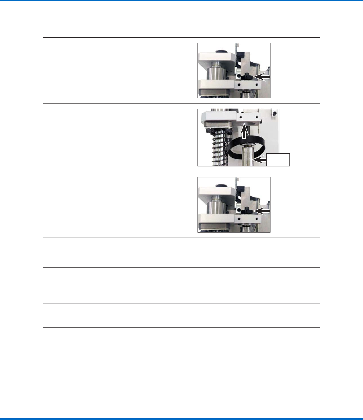
Use a 12 mm wrench to release the black block
set bolt and then remove the black block from
the threaded section of the Raxis ball spline.
9
Move the Raxis ball spline down and then
remove the old timing belt.
Raxis ball
spline
10
a. Slip the new timing belt around the Raxis
ball spline.
b. Move the ball spline back into position and
then tighten the black block set bolt to
secure it.
11
With the sawtooth sides of the new timing belt facing one another, loop the belt around the Raxis idler
and timing pulleys.
NOTE: The tension is not measured for this belt.
12
Secure the Raxis module to the Zaxis module with the two (2) screws removed previously.
13
Secure the Zaxis module to the robot with the four (4) screws previously removed.
14
Reconnect the Motor Z, Motor R, Sensor V (Raxis Reversal Optical Switch), Sensor R, and Sensor Z
cables.
Continued on next page
Replace the RAxis Timing Belt (R / RV Series Only) (continued)
Automated Dispensing Systems Maintenance & Parts Guide
32 www.nordsonefd.com info@nordsonefd.com +1-401-431-7000 Sales and service of Nordson EFD dispensing systems are available worldwide.
Timing Belt and Motor Replacement: Z and R Axes (continued)
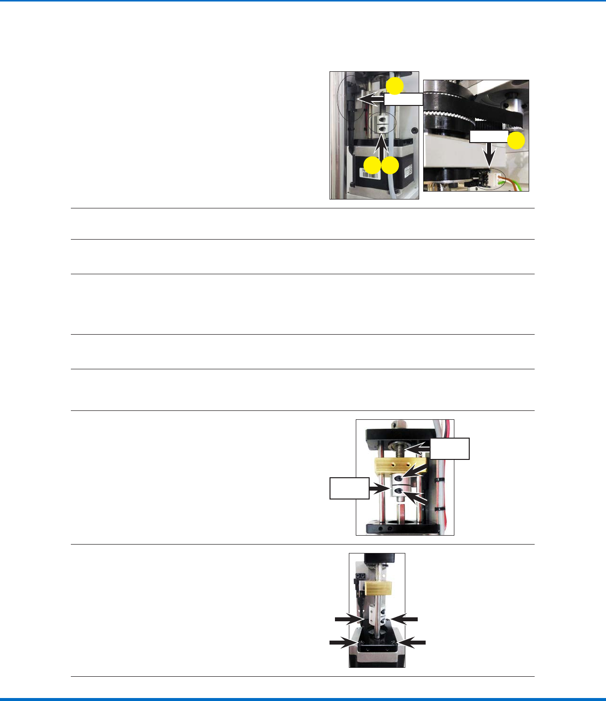
15
a. After the timing belt is fastened and all
cables are reconnected, release the two (2)
screws that attach the Raxis ball screw and
the Raxis motor shaft.
b. Power on the robot and adjust Sensor V and
Sensor R until their sensor lights are blocked
simultaneously.
c. In that position, re‑tighten the two (2) screws
that secure the Raxis ball screw and the
Raxis motor shaft.
Sensor V
Sensor R
a
b
b
c
16
Switch off the robot power before continuing to the next procedure.
Replace the ZAxis Motor (R / RV Series Only)
17
Go to “Replace the ZAxis Motor (All Units Except E2 / E2V and R / RV Series)” on page27 to
replace the Zaxis motor. Return here to continue.
NOTE: The only difference for the R / RV series is that the timing belt is angled as it exits the timing
pulley; this does not alter the motor replacement process.
Replace the RAxis Motor (R / RV Series Only)
18
Complete steps 5–7 of “Replace the RAxis Timing Belt (R / RV Series Only)” on page30 to release
the Raxis module. Return here to continue.
19
Release the two (2) screws that attach the
Raxis ball screw and the Raxis motor shaft
and push the coupling up.
Raxis
ball screw
Coupling
20
Release the four (4) screws that fasten the
Raxis motor to the Raxis module.
NOTE: The ball screw is part of the Raxis
module.
Continued on next page
Replace the RAxis Timing Belt (R / RV Series Only) (continued)
33www.nordsonefd.com info@nordsonefd.com +1-401-431-7000 Sales and service of Nordson EFD dispensing systems are available worldwide.
Automated Dispensing Systems Maintenance & Parts Guide
Timing Belt and Motor Replacement: Z and R Axes (continued)
21
Release the four (4) screws that fasten the
Raxis motor to the Raxis motor base plate.
NOTE: The screws are threaded into nuts
located underneath the Raxis motor base
plate; these nuts will fall when the screws are
released.
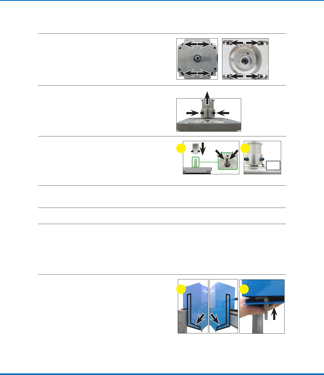
22
Remove the two (2) set screws on the timing
pulley and then pull the timing pulley away from
the motor.
23
Assemble the timing pulley onto the shaft of the
new motor; align the timing pulley such that the
two (2) set screws contact the two flat surfaces
of the motor shaft.
Ensure that the distance from the base of the
timing pulley to the top of the motor is 6 mm
(0.24").
6 mm
(0.24")
a b
24
Secure the new Raxis motor and timing pulley to the Raxis motor base plate with the four (4) screws
and nuts removed previously.
25
Secure the Raxis motor to the Raxis module with the four (4) screws removed previously.
26
Complete steps 11–15 of “Replace the RAxis Timing Belt (R / RV Series Only)” on page30 to
complete the maintenance process. Return here to continue.
NOTE: The only exception is that in step 15, the Raxis ball screw and motor shaft will already be
detached.
Reinstall the ZAxis Cover (R / RV Series Only)
27
a. Position the Zaxis cover over the Zaxis
module and vertically lower it to its correct
orientation.
b. Lift up the Zaxis bottom plate and secure
the two components with the 10 screws
removed previously.
ba
Replace the RAxis Motor (R / RV Series Only)