Nordson_EFD_Automated_Dispensing_Systems_Maintenance_Guide - 第34页
Automated Dispensing Systems Maintenance & Parts Guide 34 www.nordsonefd.com info@nordsonefd.com +1-401-431-7000 Sales and service of Nordson EFD dispensing systems are available worldwide. ZAxis Spring Replacement …
33www.nordsonefd.com info@nordsonefd.com +1-401-431-7000 Sales and service of Nordson EFD dispensing systems are available worldwide.
Automated Dispensing Systems Maintenance & Parts Guide
Timing Belt and Motor Replacement: Z and R Axes (continued)
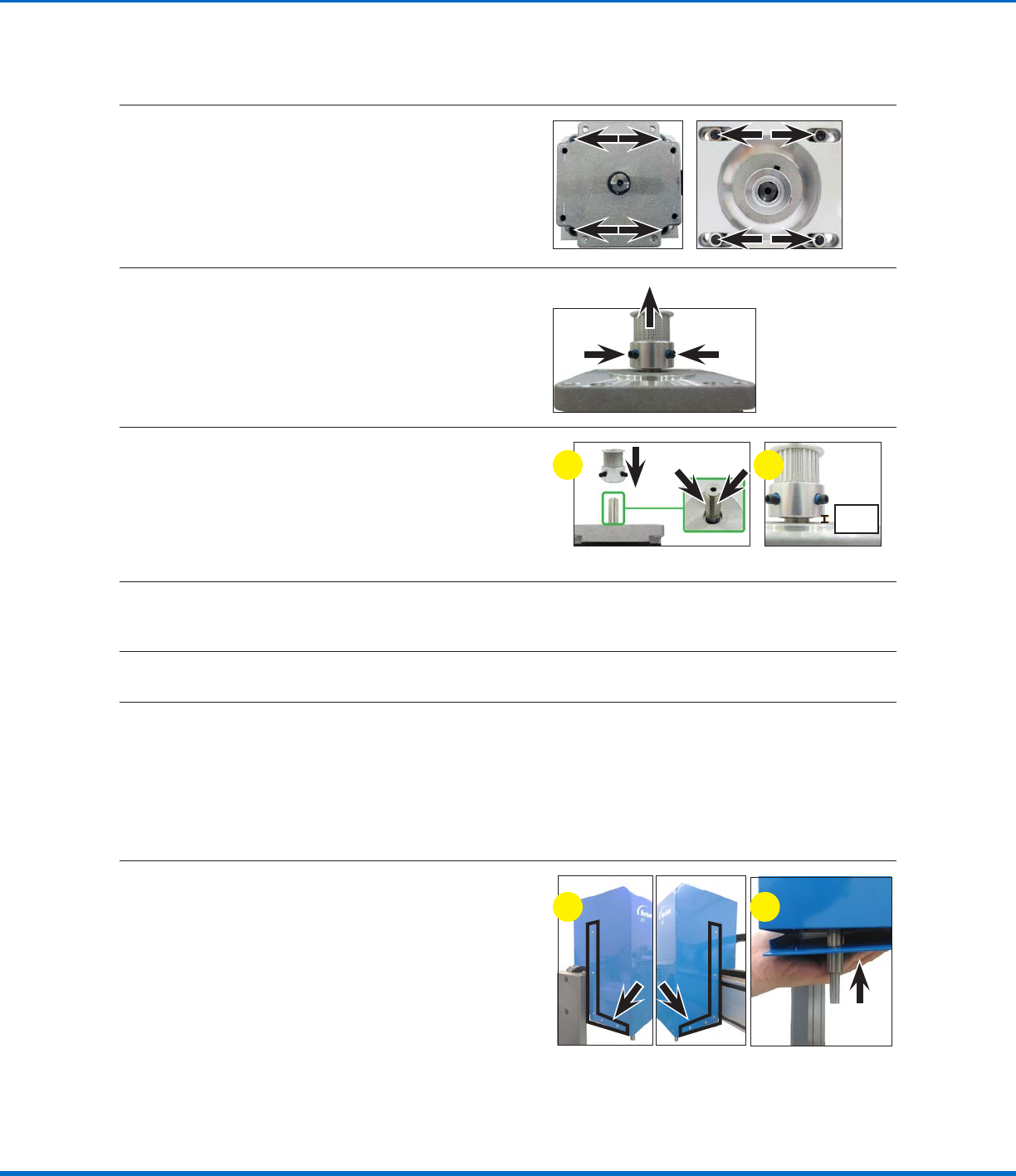
21
Release the four (4) screws that fasten the
Raxis motor to the Raxis motor base plate.
NOTE: The screws are threaded into nuts
located underneath the Raxis motor base
plate; these nuts will fall when the screws are
released.
22
Remove the two (2) set screws on the timing
pulley and then pull the timing pulley away from
the motor.
23
Assemble the timing pulley onto the shaft of the
new motor; align the timing pulley such that the
two (2) set screws contact the two flat surfaces
of the motor shaft.
Ensure that the distance from the base of the
timing pulley to the top of the motor is 6 mm
(0.24").
6 mm
(0.24")
a b
24
Secure the new Raxis motor and timing pulley to the Raxis motor base plate with the four (4) screws
and nuts removed previously.
25
Secure the Raxis motor to the Raxis module with the four (4) screws removed previously.
26
Complete steps 11–15 of “Replace the RAxis Timing Belt (R / RV Series Only)” on page30 to
complete the maintenance process. Return here to continue.
NOTE: The only exception is that in step 15, the Raxis ball screw and motor shaft will already be
detached.
Reinstall the ZAxis Cover (R / RV Series Only)
27
a. Position the Zaxis cover over the Zaxis
module and vertically lower it to its correct
orientation.
b. Lift up the Zaxis bottom plate and secure
the two components with the 10 screws
removed previously.
ba
Replace the RAxis Motor (R / RV Series Only)
Automated Dispensing Systems Maintenance & Parts Guide
34 www.nordsonefd.com info@nordsonefd.com +1-401-431-7000 Sales and service of Nordson EFD dispensing systems are available worldwide.
ZAxis Spring Replacement (E and EV Series Only)
CAUTION
Risk of injury or equipment damage. Before performing any service procedure, complete the steps under
“Preparation for all Service Procedures” on page3.
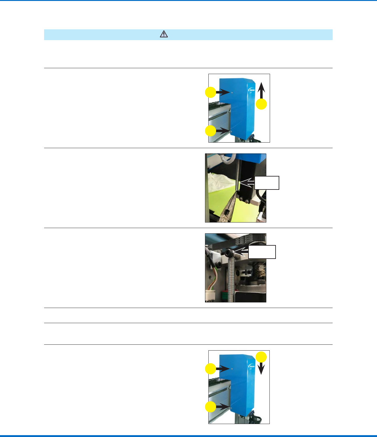
1
a. Remove the four (4) screws that secure the
Zaxis cover to the Zaxis module.
b. Pull up vertically to remove the Zaxis cover.
a
b
a
2
While keeping the Zaxis head in the top
position, grasp the bottom of the Zaxis spring
and then pull it down and push it towards the
back of the robot to release it from the retaining
lip.
Z axis
spring
3
Remove the screw that secures the Zaxis
spring; this frees the spring.
Z axis spring
screw
4
Secure the replacement Zaxis spring with the screw removed previously.
5
Grasp the bottom of the Zaxis spring and then pull it down and place the bottom loop inside the
retaining lip.
6
a. Reinstall the Zaxis cover.
b. Secure the cover with the screws removed
previously.
b
a
b
35www.nordsonefd.com info@nordsonefd.com +1-401-431-7000 Sales and service of Nordson EFD dispensing systems are available worldwide.
Automated Dispensing Systems Maintenance & Parts Guide
Fuse Replacement
CAUTION
Risk of injury or equipment damage. Before performing any service procedure, complete the steps under
“Preparation for all Service Procedures” on page3.
Fuse Replacement (P/N 7361392 — All Units Except E2) (P/N 7361391 — E2 Units)
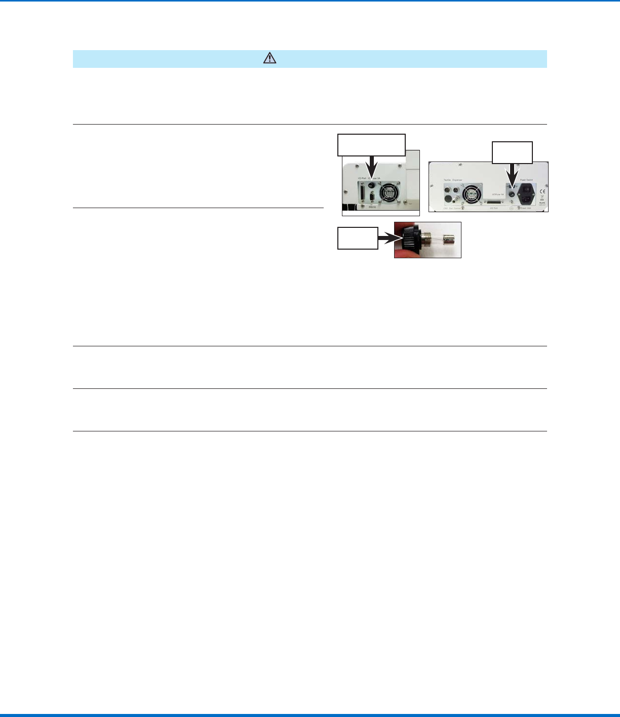
1
Unscrew the robot fuse holder (P/N 7361394)
and remove the fuse.
NOTE: The fuse is located on the left side of the
control assembly cover on all models except
E2 units. On E2 units, the fuse is located on the
right side of the control assembly cover.
E2 fuse
location
Fuse location for all
units except E2
Robot fuse
holder
2
Visually inspect the fuse for a broken wire or
a scorched cylinder that is brown or black in
color; these are signs of a blown fuse.
NOTE: You can also use a multimeter to check
the fuse: With the multimeter in resistance
mode, touch the metal tips of the testing leads
to the metal ends of the fuse. If the resistance
displayed does not change (thus remaining at a
100% resistance state), then the fuse is blown.
If a small resistance is measured, then the fuse
is good.
3
(All units except E2)
If the fuse is blown, remove it from the robot fuse holder install a new 20 mm, 3 A fuse (P/N7361392).
(E2 units only)
If the fuse is blown, remove it from the robot fuse holder install a new 20 mm, 1 A fuse (P/N7361391).
4
Reinstall the robot fuse holder in the robot.