Nordson_EFD_Automated_Dispensing_Systems_Maintenance_Guide - 第36页
Automated Dispensing Systems Maintenance & Parts Guide 36 www.nordsonefd.com info@nordsonefd.com +1-401-431-7000 Sales and service of Nordson EFD dispensing systems are available worldwide. Fuse Replacement (P/N 7361…
35www.nordsonefd.com info@nordsonefd.com +1-401-431-7000 Sales and service of Nordson EFD dispensing systems are available worldwide.
Automated Dispensing Systems Maintenance & Parts Guide
Fuse Replacement
CAUTION
Risk of injury or equipment damage. Before performing any service procedure, complete the steps under
“Preparation for all Service Procedures” on page3.
Fuse Replacement (P/N 7361392 — All Units Except E2) (P/N 7361391 — E2 Units)
1
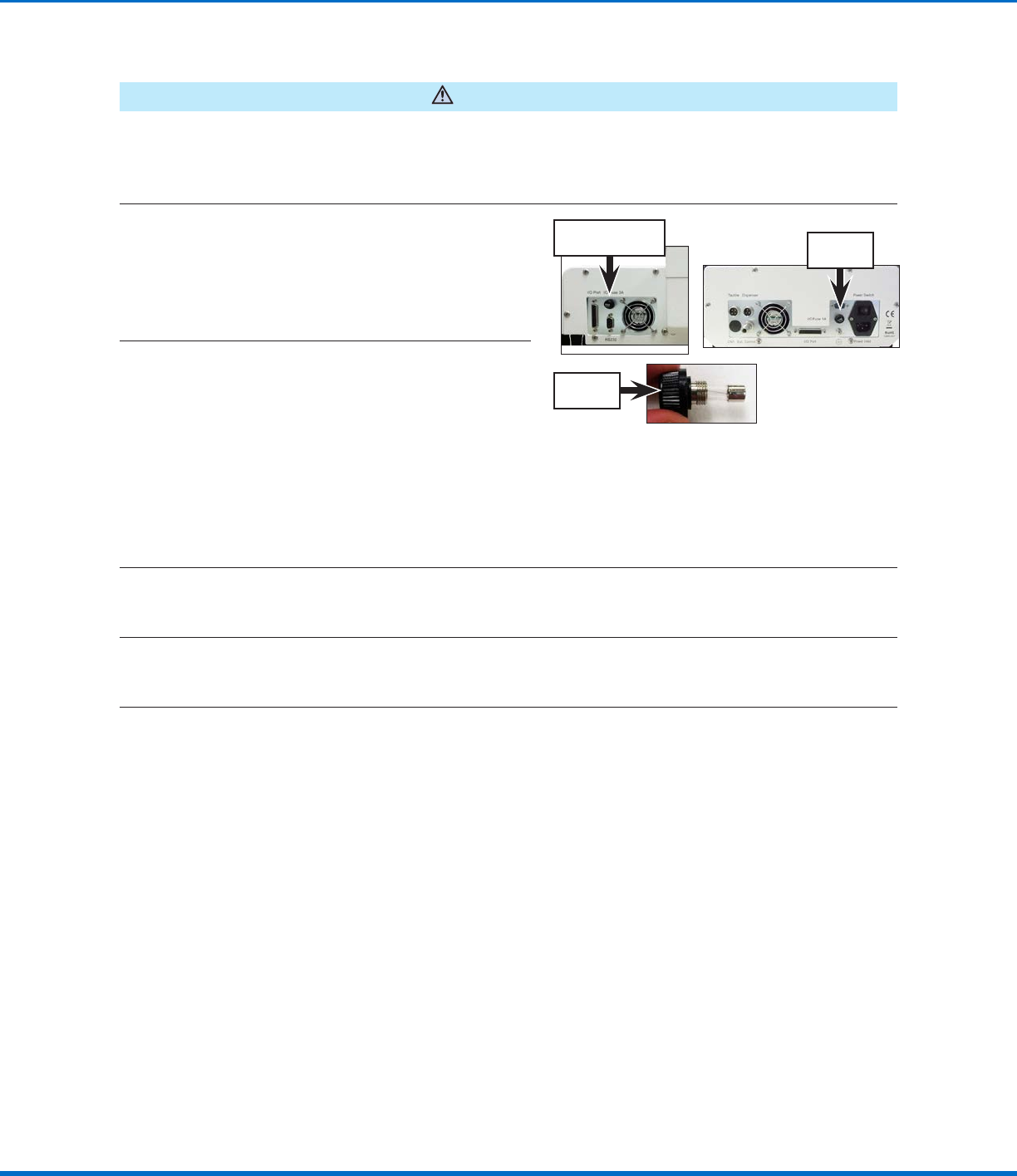
Unscrew the robot fuse holder (P/N 7361394)
and remove the fuse.
NOTE: The fuse is located on the left side of the
control assembly cover on all models except
E2 units. On E2 units, the fuse is located on the
right side of the control assembly cover.
E2 fuse
location
Fuse location for all
units except E2
Robot fuse
holder
2
Visually inspect the fuse for a broken wire or
a scorched cylinder that is brown or black in
color; these are signs of a blown fuse.
NOTE: You can also use a multimeter to check
the fuse: With the multimeter in resistance
mode, touch the metal tips of the testing leads
to the metal ends of the fuse. If the resistance
displayed does not change (thus remaining at a
100% resistance state), then the fuse is blown.
If a small resistance is measured, then the fuse
is good.
3
(All units except E2)
If the fuse is blown, remove it from the robot fuse holder install a new 20 mm, 3 A fuse (P/N7361392).
(E2 units only)
If the fuse is blown, remove it from the robot fuse holder install a new 20 mm, 1 A fuse (P/N7361391).
4
Reinstall the robot fuse holder in the robot.
Automated Dispensing Systems Maintenance & Parts Guide
36 www.nordsonefd.com info@nordsonefd.com +1-401-431-7000 Sales and service of Nordson EFD dispensing systems are available worldwide.
Fuse Replacement (P/N 7361393 — All Units Except E2)
1
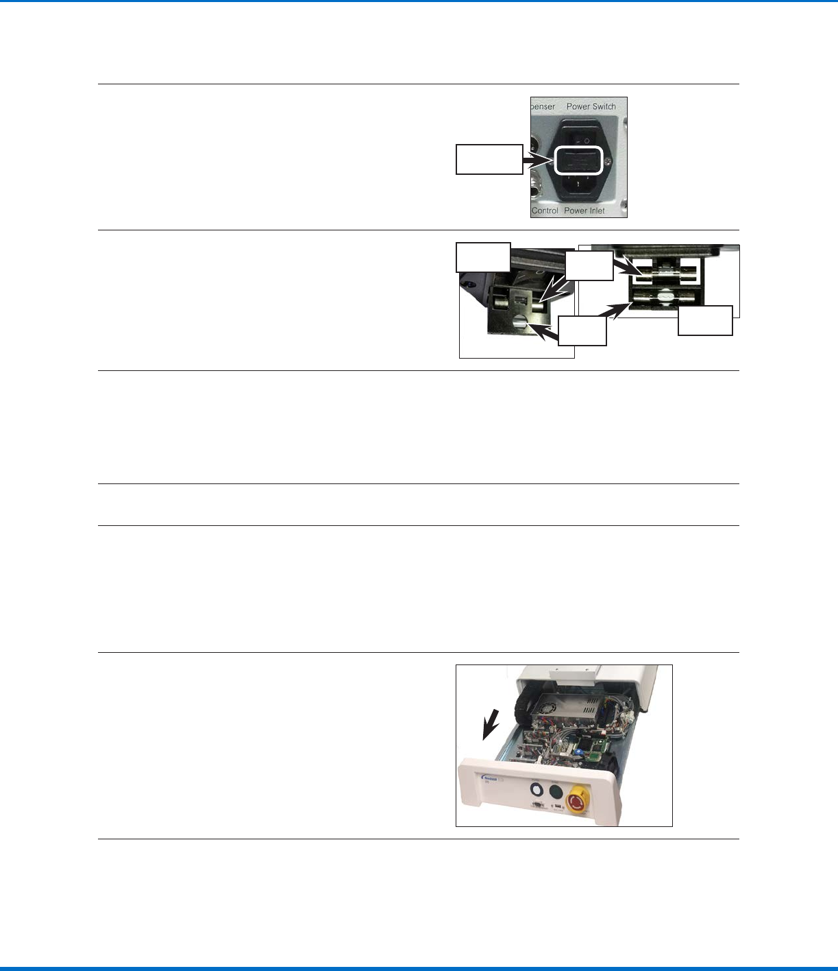
Open the fuse release latch located between
the Power Switch and the Power Inlet. The latch
has a fuse symbol on it.
Fuse release
latch
2
Pull open the spare‑fuse holder.
NOTE: The spare‑fuse holder includes two
fuses. The fuse closest to the exterior face is in
storage and the far side fuse is in use.
Top view
Bottom
view
Stored
fuse
Fuse in
use
3
Visually inspect the fuse for a broken wire or a scorched cylinder that is brown or black in color; these
are signs of a blown fuse.
NOTE: You can also use a multimeter to check the fuse: With the multimeter in resistance mode, touch
the metal tips of the testing leads to the metal ends of the fuse. If the resistance displayed does not
change (thus remaining at a 100% resistance state), then the fuse is blown. If a small resistance is
measured, then the fuse is good.
4
Remove the blown fuse from the spare fuse holder and install a new fuse.
5
Reinstall the spare fuse holder with the new fuse in the power socket.
Fuse Replacement (continued)
I/O Microfuse Replacement
1
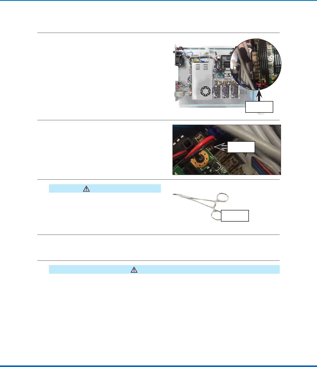
Remove the control assembly. Refer to the
applicable steps under “Remove and Clean the
Control Assembly” on page14 to remove the
control assembly. Return here to continue.
Continued on next page
37www.nordsonefd.com info@nordsonefd.com +1-401-431-7000 Sales and service of Nordson EFD dispensing systems are available worldwide.
Automated Dispensing Systems Maintenance & Parts Guide
2
Locate the microfuses on printed circuit
boardB. The microfuses are very small.
I/O microfuses
3
Use a multimeter to check microfuse 1A (the
main output microfuse): With the multimeter
in resistance mode, touch the metal tips of
the testing leads to the metal ends of the
microfuse. If the resistance displayed does not
change (thus remaining at a 100% resistance
state), then the microfuse is blown. If a small
resistance is measured, then the microfuse is
good.
Microfuse 1A
4
CAUTION
Avoid pinching or grasping the small tabs that hold
the microfuse; doing so can permanently damage the
microfuse holder.
If the microfuse is blown, use needle‑nose pliers
or a fine hemostat to remove the microfuse and
to reinstall a replacement microfuse.
Typical
hemostat tool
5
Visually inspect the other microfuses for a broken wire or a scorched cylinder that is brown or black in
color; these are signs of a blown microfuse.
NOTE: You can also use a multimeter to check the microfuses (same instructions as in step 3).
6
CAUTION
Avoid pinching or grasping the small tabs that hold the microfuse; doing so can permanently damage the
microfuse holder.
If a microfuse is blown, use needle‑nose pliers or a fine hemostat to remove the microfuse and to
reinstall a replacement microfuse.
I/O Microfuse Replacement (continued)
Fuse Replacement (continued)