KY8030 Programmers Manual - 第17页
Program mers Manual | 1 5 ※ Note: Y ou can add, modify or remove a pad and pattern by using the pad bar . If the pattern is not created automatical ly , the user can regist er it manuall y by selecting or . 8) In order t…
14 | KY-8030 Series(KYOS-2007001_rev0)
3DIn‐lineSolderPasteInspectionSystems
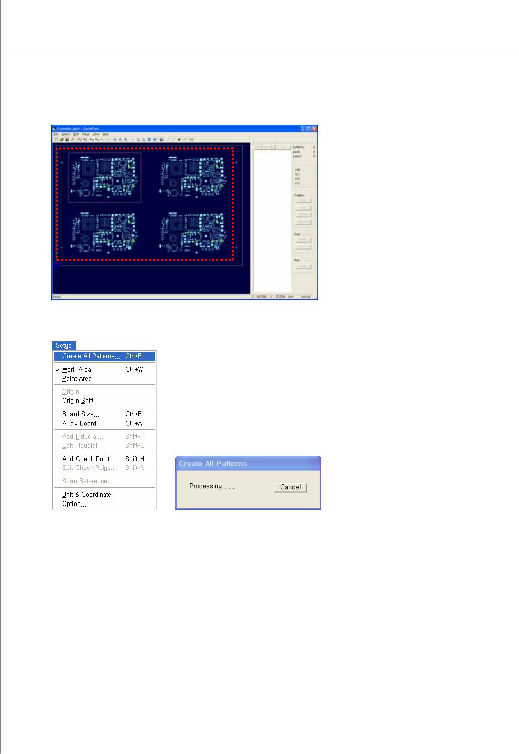
6) Select a desired work area by dragging your mouse.
7) Select “Setup ▶ Create All Patterns” from the menu bar.
The program will create patterns while showing you the progress via the "Create All
Patterns" window.
Programmers Manual
| 15
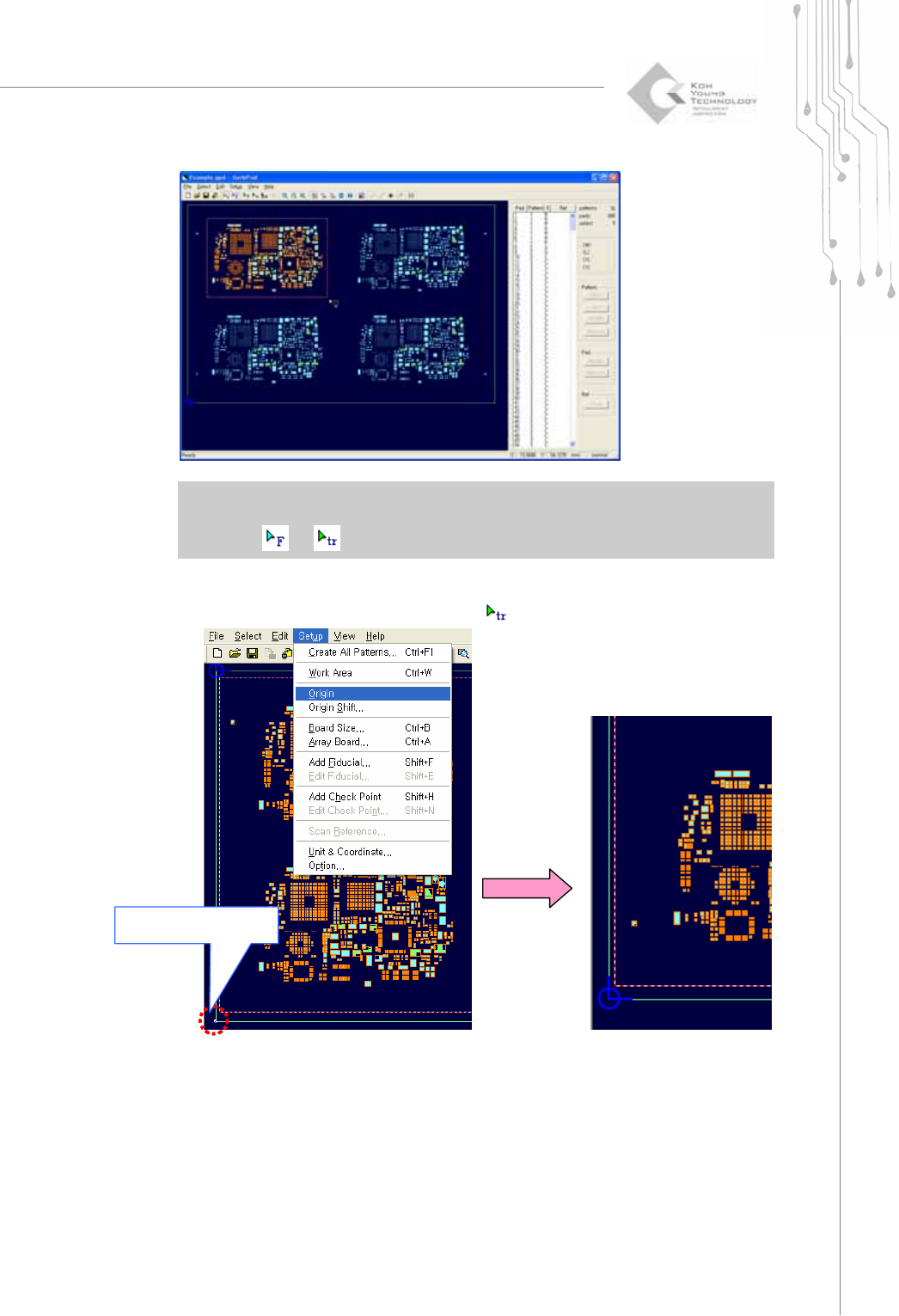
※ Note: You can add, modify or remove a pad and pattern by using the pad bar.
If the pattern is not created automatically, the user can register it manually by selecting
or .
8) In order to set the left bottom side of the PCB as Origin, drag and select one of
apexes of outer line or point after selecting
.
Select left bottom side
with Trace
16 | KY-8030 Series(KYOS-2007001_rev0)
3DIn‐lineSolderPasteInspectionSystems
9) Select "Setup ▶ Origin" from the menu bar.
Then the desired point in the PCB to set it as the coordinates origin.
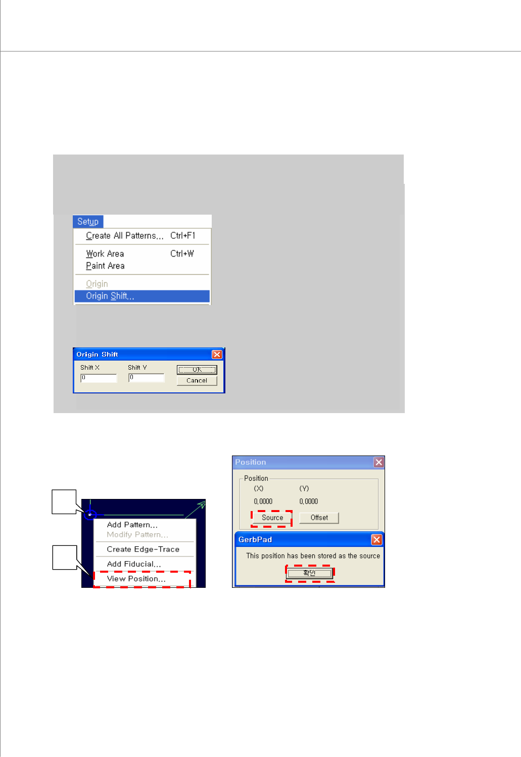
※ Note: Instead of going through steps 8) ~ 9), you can also set the origin via “Origin Shift” as
follows:
a) Select “Setup ▶ Origin Shift” from the menu bar.
b) Enter relative coordinates (X, Y) in reference to the existing origin for the PCB and click the OK button. The
origin will be shifted by the coordinates (X, Y) just entered.
10) In order to set the board size, select the left bottom side of PCB with Trace then right
click. Select View Position and click Source.
①
②
③
④