KY8030 Programmers Manual - 第47页
Program mers Manual | 4 5 4) Origin Set the center point of the selected flas h, trace or pad as the origin f or a PCB. ※ Note: Because the initi al origin provided by a Gerb er file is set during the design, it may exis…
44 | KY-8030 Series(KYOS-2007001_rev0)
3DIn‐lineSolderPasteInspectionSystems
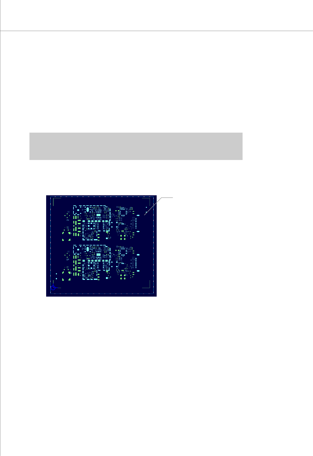
3) Paint Area
Change the mouse pointer mode to Paint Area Selection mode.
You can add, remove or resize a paint area.
(1) Add: Select a paint area by dragging your mouse. The rectangular area created
by the mouse drag will be set as a paint area.
(2) Remove: Click your mouse over the paint space that you want to remove.
(3) Resize: Move the mouse pointer over the center of each side of the paint area.
When the shape of the mouse pointer is changed to a bi-directional
arrow, resize the paint area by dragging your mouse.
※ Note: You can specify up to 40 work and paint areas altogether.
※ Caution: Specify a paint area before performing the "Paint" task. Otherwise, unnecessary parts
may be included in the picture file.
You can perform the following tasks in relation to a paint area.
(1) Choose "File ▶ Paint" in the menu bar.
Picture Area
Programmers Manual
| 45
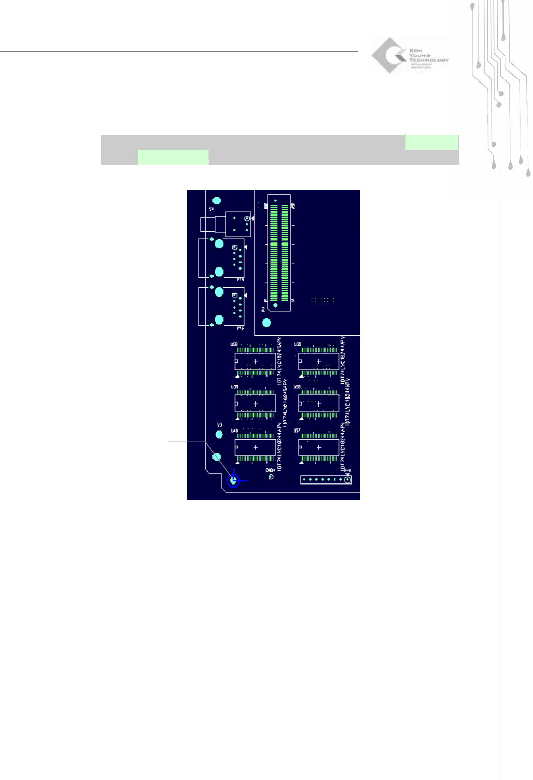
4) Origin
Set the center point of the selected flash, trace or pad as the origin for a PCB.
※ Note: Because the initial origin provided by a Gerber file is set during the design, it may exist on
the inside of a PCB. The origin should be set to the left bottom side of the actual PCB.
Setting the center
point of the selected
flash
(
Pad
)
46 | KY-8030 Series(KYOS-2007001_rev0)
3DIn‐lineSolderPasteInspectionSystems
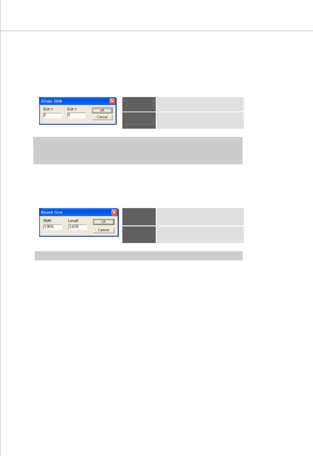
5) Origin Shift
Open the "Origin Shift" dialog box to change the position of the current origin.
The "Origin Shift" Dialog Box
Shift X
Displacement of the origin in the X-
axis.
Shift Y
Displacement of the origin in the Y-
axis.
※ Note:
y If you enter "0" for both Shift X and Shift Y, the position of the origin will not be changed.
y The origin will be moved by Shift X and Shift Y values along the PCB coordinates.
6) Board Size
Open the "Board Size" dialog box to enter the size of a PCB.
The "Board Size" Dialog Box
Width
The width of the PCB
Length
The length of the PCB.
※ Note: You can use the "Position" function to set the width and length values automatically.