KY8030 Programmers Manual - 第64页
62 | KY-8030 Series (KYOS-2007001_rev0) 3D In ‐ line Solder Paste Inspection Systems 1.5. P AD File specifications ● Specifi cations @HEADER Version= <nVers ionNo> Unit =<szUnit> Coordinate =< …
Programmers Manual
| 61
● Trace
It is a defined straight line data which is included in the Stencil and Mask plane of the
Gerber file. It is a data that is required to process a Board by moving along the
straight line with a straight-sided or circular tool.
● Pad
It is a part of the PCB. It is the part which is soldered and applied with lead. There
are 2 types of Pads. One is the SMD type Pad in which the SMD type parts are put,
and the other is the Hole type Pad in which Through-Hole type parts are inserted.
● Pattern
It is a group of the Flash and Trace which are connected with each other and their
shapes, sizes and angles are same. All the Pads, letters and symbols that exist on
the Mask (Stencil) are patterns. Generally a group of many Pads is used as a Pattern.
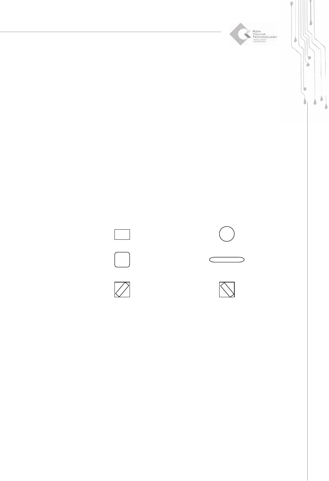
● Shape
It is a shape data which is used for Patterns, Pads and Apertures.
Example)
rectangle (Rectangle) Circle (Circle)
Rounded Rectangle (Rounded Rectangle) Oblong (Oblong)
P-type (Positive Sloped Rect.) N-type (Negative Sloped Rect.)
Other (Undefined)
● Reference
It is a name of the components. It is used for distinguishing the positions of the
components on the PCB.
● Pattern data
It is a Pattern information.
Shapes, X axis position, Y axis position, reference
62 | KY-8030 Series(KYOS-2007001_rev0)
3DIn‐lineSolderPasteInspectionSystems
1.5. PAD File specifications
● Specifications
@HEADER
Version= <nVersionNo>
Unit=<szUnit>
Coordinate=<szCoordinate>
OffsetX=<fOffsetX>
OffsetY=<fOffsetY>
Arrays=<nArrays>
Fiducials=<nFiducials>
CheckPoints=<nCheckPoints>
Patterns=<nPatterns>
Pads=<nPads>
@BOARD
<fBoardSizeX> <fBoardSizeY>
@ARRAY
<nArrayNo> <fShiftX> <fShiftY> < fShiftR>
@FIDUCIAL
<nFidNo> <cFidType> <cFidShape> <fFidX> <fFidY> <fFidSizeX> <fFidSizeY> <fFidOffsetX>
<fFidOffsetY> <dbsRefCode>
@CHECKPOINT
<nCheckPointNo> <fCheckPointX> <fCheckPointY>
@PATTERN
<nPatternNo> <cShape> <fPatternSizeX> <fPatternSizeY> <fPatternOffsetX> <fPatternOffsetY>
<fPatternArea> <fPatternAngle>
@PAD
<nPadNo> <nPatternNo> <fPadX> <fPadY> <dbsRefCode>
@END
Programmers Manual
| 63
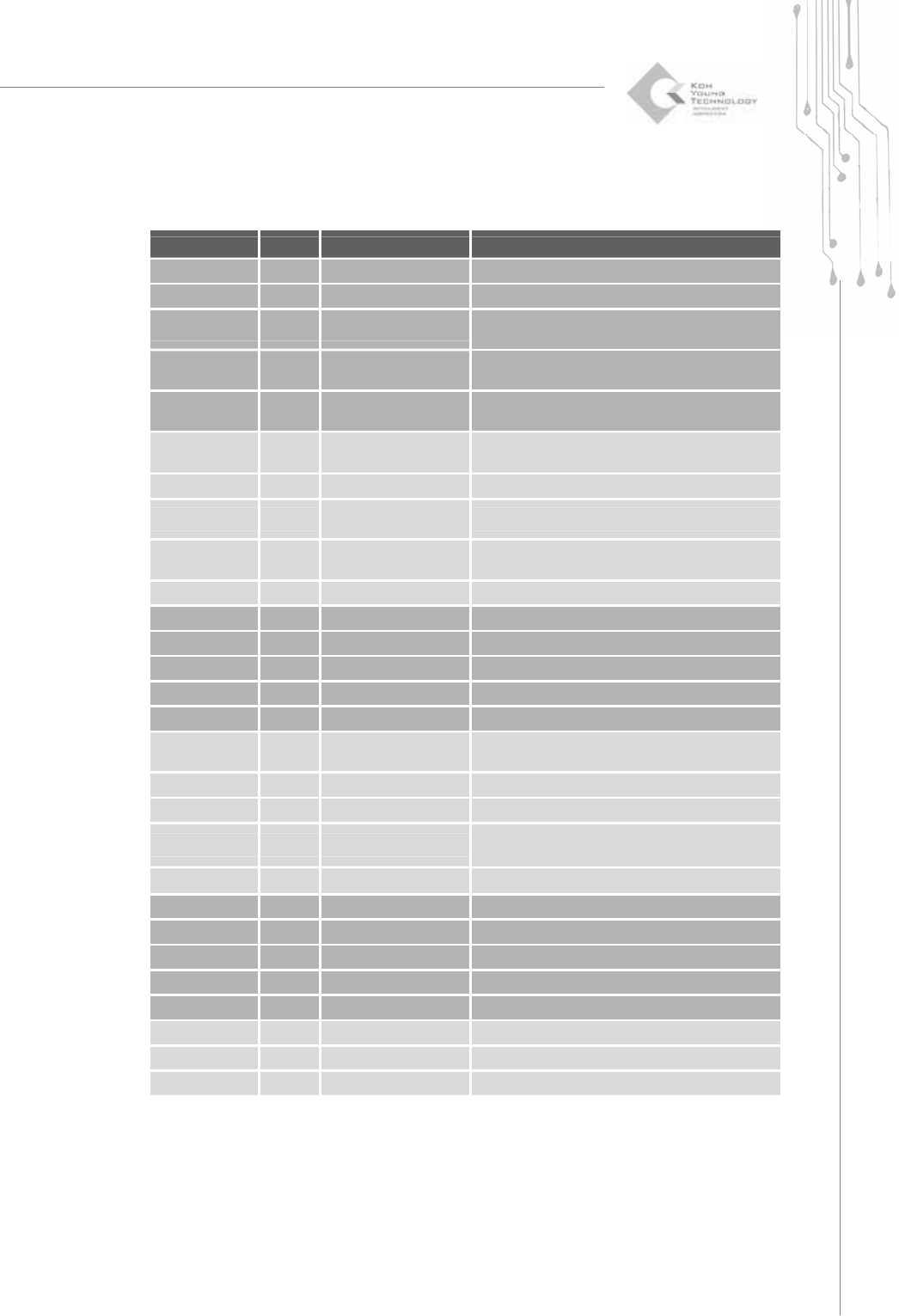
● Standards
Items Type Definition Remarks
nVersionNo int PAD file version 7
szUnit char* Unit system MM (mm) / INCH (inch)
szCoordinate char* Coordinate system
LL(lower left)/LR(lower right)/UL(upper left)/UR(upper
right)
fOffsetX double Origin Offset X
X coordinate value of PCB origin based on the
design origin
fOffsetY double Origin Offset Y
Y coordinate value of PCB origin based on the
design origin
nArrays int Total number of Arrays Standard value = 1
nFiducials int Total number of Fiducials
nCheckPoints int
Total number of
Checkpoints
nPatterns int
Total number of
Patterns
nPads int Total number of Pads
fBoardSizeX double PCB size (Width)
fBoardSizeY double PCB size (Length)
nArrayNo int PCB No. PCB No.1 is the standard PCB.
fShiftX double Array PCB position (X) Distance value moved from the standard PCB
fShiftY double Array PCB position (Y) Distance value moved from the standard PCB
nShiftR int Array PCB angle, deg
Distance value moved from the standard PCB
(0,90,-90,180)
nFidNo int Fiducial No.
cFidType char Fiducial type G (global) / A (array) / L (local)
cFidShape char Fiducial shape
R (rectangle) / C (circle) / U (undefined)
D (rounded rectangle) / O (Oblong)
fFidX double Fiducial position X
fFidY double Fiducial position Y
fFidSizeX double Fiducial size (Width)
fFidSizeY double Fiducial size (Length)
fFidOffsetX double Fiducial Offset X Centroid X - Center of Area X
fFidOffsetY double Fiducial Offset Y Centroid Y - Center of Area Y
dbsRefCode “char*” Reference Local Fiducial: “R1”, “C2”,Global Fiducial:: “”
nCheckPointNo Int Checkpoint No.
fCheckPointX double Checkpoint position X