GDM 13-34切石基说明书.pdf - 第7页
English | 7 Bosch Power Tools 1 609 92A 41D | (19.10.17) Do not attach a saw chain, woodcarving blade, seg- mented diamond wheel with a peripheral gap greater than 10 mm or toothed saw blade. Such blades create frequen…
6 | English
1 609 92A 41D | (19.10.17) Bosch Power Tools
Cut-off machine safety warnings
The guard provided with the tool must be securely
attached to the power tool and positioned for maxi-
mum safety, so the least amount of wheel is exposed
towards the operator. Position yourself and bystand-
ers away from the plane of the rotating wheel. The
guard helps to protect operator from broken wheel frag-
ments and accidental contact with wheel.
Use only diamond cut-off wheels for your power tool.
Just because an accessory can be attached to your power
tool, it does not assure safe operation.
The rated speed of the accessory must be at least equal
to the maximum speed marked on the power tool.
Accessories running faster than their rated speed can
break and fly apart.
Wheels must be used only for recommended applica-
tions. For example: do not grind with the side of cut-off
wheel. Abrasive cut-off wheels are intended for peripheral
grinding, side forces applied to these wheels may cause
them to shatter.
Always use undamaged wheel flanges that are of cor-
rect diameter for your selected wheel. Proper wheel
flanges support the wheel thus reducing the possibility of
wheel breakage.
The outside diameter and the thickness of your acces-
sory must be within the capacity rating of your power
tool. Incorrectly sized accessories cannot be adequately
controlled.
The arbour size of wheels and flanges must properly fit
the spindle of the power tool. Wheels and flanges with
arbour holes that do not match the mounting hardware of
the power tool will run out of balance, vibrate excessively
and may cause loss of control.
Do not use damaged wheels. Before each use, inspect
the wheels for chips and cracks. If power tool or wheel
is dropped, inspect for damage or install an undam-
aged wheel. After inspecting and installing the wheel,
position yourself and bystanders away from the plane
of the rotating wheel and run the power tool at maxi-
mum no load speed for one minute. Damaged wheels will
normally break apart during this test time.
Wear personal protective equipment. Depending on
application, use face shield, safety goggles or safety
glasses. As appropriate, wear dust mask, hearing pro-
tectors, gloves and workshop apron capable of stop-
ping small abrasive or workpiece fragments. The eye
protection must be capable of stopping flying debris gen-
erated by various operations. The dust mask or respirator
must be capable of filtrating particles generated by your
operation. Prolonged exposure to high intensity noise may
cause hearing loss.
Keep bystanders a safe distance away from work area.
Anyone entering the work area must wear personal
protective equipment. Fragments of workpiece or of a
broken accessory may fly away and cause injury beyond
immediate area of operation.
Hold the power tool by insulated gripping surfaces
only, when performing an operation where the cutting
accessory may contact hidden wiring or its own cord.
Cutting accessory contacting a “live” wire may make ex-
posed metal parts of the power tool “live” and could give
the operator an electric shock.
Position the cord clear of the spinning accessory. If you
lose control, the cord may be cut or snagged and your hand
or arm may be pulled into the spinning wheel.
Never lay the power tool down until the accessory has
come to a complete stop. The spinning wheel may grab
the surface and pull the power tool out of your control.
Do not run the power tool while carrying it at your side.
Accidental contact with the spinning accessory could snag
your clothing, pulling the accessory into your body.
Regularly clean the power tool’s air vents. The motor’s
fan will draw the dust inside the housing and excessive
accumulation of powdered metal may cause electrical
hazards.
Do not operate the power tool near flammable materi-
als. Sparks could ignite these materials.
Do not use accessories that require liquid coolants.
Using water or other liquid coolants may result in electro-
cution or shock.
Kickback and related warnings
Kickback is a sudden reaction to a pinched or snagged ro-
tating wheel. Pinching or snagging causes rapid stalling of
the rotating wheel which in turn causes the uncontrolled
power tool to be forced in the direction opposite of the
wheel’s rotation at the point of the binding.
For example, if an abrasive wheel is snagged or pinched by
the workpiece, the edge of the wheel that is entering into
the pinch point can dig into the surface of the material
causing the wheel to climb out or kick out. The wheel may
either jump toward or away from the operator, depending
on direction of the wheel’s movement at the point of pinch-
ing. Abrasive wheels may also break under these condi-
tions.
Kickback is the result of power tool misuse and/or incor-
rect operating procedures or conditions and can be avoid-
ed by taking proper precautions as given below.
Maintain a firm grip on the power tool and position your
body and arm to allow you to resist kickback forces.
Always use auxiliary handle, if provided, for maximum
control over kickback or torque reaction during
start-up. The operator can control torque reactions or
kickback forces, if proper precautions are taken.
Never place your hand near the rotating accessory.
Accessory may kickback over your hand.
Do not position your body in line with the rotating
wheel. Kickback will propel the tool in direction opposite
to the wheel’s movement at the point of snagging.
Use special care when working corners, sharp edges,
etc. Avoid bouncing and snagging the accessory. Cor-
ners, sharp edges or bouncing have a tendency to snag the
rotating accessory and cause loss of control or kickback.
OBJ_DOKU-29567-004.fm Page 6 Thursday, October 19, 2017 2:24 PM
English | 7
Bosch Power Tools 1 609 92A 41D | (19.10.17)
Do not attach a saw chain, woodcarving blade, seg-
mented diamond wheel with a peripheral gap greater
than 10 mm or toothed saw blade. Such blades create
frequent kickback and loss of control.
Do not “jam” a cut-off wheel or apply excessive pres-
sure. Do not attempt to make an excessive depth of cut.
Overstressing the wheel increases the loading and suscep-
tibility to twisting or snagging of the wheel in the cut and
the possibility of kickback or wheel breakage.
When wheel is binding or when interrupting a cut for
any reason, switch off the power tool and hold the
power tool motionless until the wheel comes to a com-
plete stop. Never attempt to remove the wheel from
the cut while the wheel is in motion otherwise kickback
may occur. Investigate and take corrective action to elimi-
nate the cause of wheel binding.
Do not restart the cutting operation in the workpiece.
Let the wheel reach full speed and carefully re-enter
the cut. The wheel may bind, walk up or kickback if the
power tool is restarted in the workpiece.
Support panels or any oversized workpiece to minimize
the risk of wheel pinching and kickback. Large work-
pieces tend to sag under their own weight. Supports must
be placed under the workpiece near the line of cut and near
the edge of the workpiece on both sides of the wheel.
Use extra caution when making a “pocket cut” into ex-
isting walls or other blind areas. The protruding wheel
may cut gas or water pipes, electrical wiring or objects that
can cause kickback.
Additional safety warnings
Wear safety goggles.
Wear a dust respirator.
Use clamps or another practical way to secure and
support the workpiece to a stable platform. Holding the
work by your hand or against the body leaves it unstable
and may lead to loss of control.
Wear hearing protection, safety goggles, dust mask
and gloves. As dust mask, use at least a particle filter-
ing half mask of filter class FFP 2.
Use suitable detectors to determine if utility lines are
hidden in the work area or call the local utility company
for assistance. Contact with electric lines can lead to fire
and electric shock. Damaging a gas line can lead to explo-
sion. Penetrating a water line causes property damage or
may cause an electric shock.
Do not touch the cutting disc after working before it
has cooled. The cutting disc becomes very hot while work-
ing.
Products sold in GB only: Your product is fitted with a
BS 1363/A approved electric plug with internal fuse
(ASTA approved to BS 1362).
If the plug is not suitable for your socket outlets, it should
be cut off and an appropriate plug fitted in its place by an
authorised customer service agent. The replacement plug
should have the same fuse rating as the original plug.
The severed plug must be disposed of to avoid a possible
shock hazard and should never be inserted into a mains
socket elsewhere.
Product Description and
Specifications
Read all safety warnings and all instruc-
tions. Failure to follow the warnings and in-
structions may result in electric shock, fire
and/or serious injury.
Intended Use
With firm support of the base plate and using the blade guard,
the machine is intended for horizontal cutting or slotting of
mainly mineral materials such as marble without the use of
water. The machine is not intended for cutting in wood,
plastic or metal.
Product Features
The numbering of the product features refers to the
illustration of the machine on the graphics page.
1 On/Off switch
2 Lock-on button for On/Off switch
3 Cutting-depth scale
4 Wing bolt for cutting depth preselection
5 Direction-of-rotation arrow for grinding spindle
6 Blade guard
7 Cutting mark, 0°
8 Cutting mark, 45°
9 Wing bolt for bevel-angle preselection
10 Base plate
11 Cutting angle scale
12 Handle (insulated gripping surface)
13 Drive spindle
14 Mounting flange
15 Diamond cutting disc*
16 Clamping flange
17 Ring spanner
18 Clamping bolt
19 Hex key
20 Wing bolt for parallel guide*
21 Parallel guide*
*Accessories shown or described are not part of the standard de-
livery scope of the product. A complete overview of accessories
can be found in our accessories program.
OBJ_DOKU-29567-004.fm Page 7 Thursday, October 19, 2017 2:24 PM
8 | English
1 609 92A 41D | (26.9.17) Bosch Power Tools
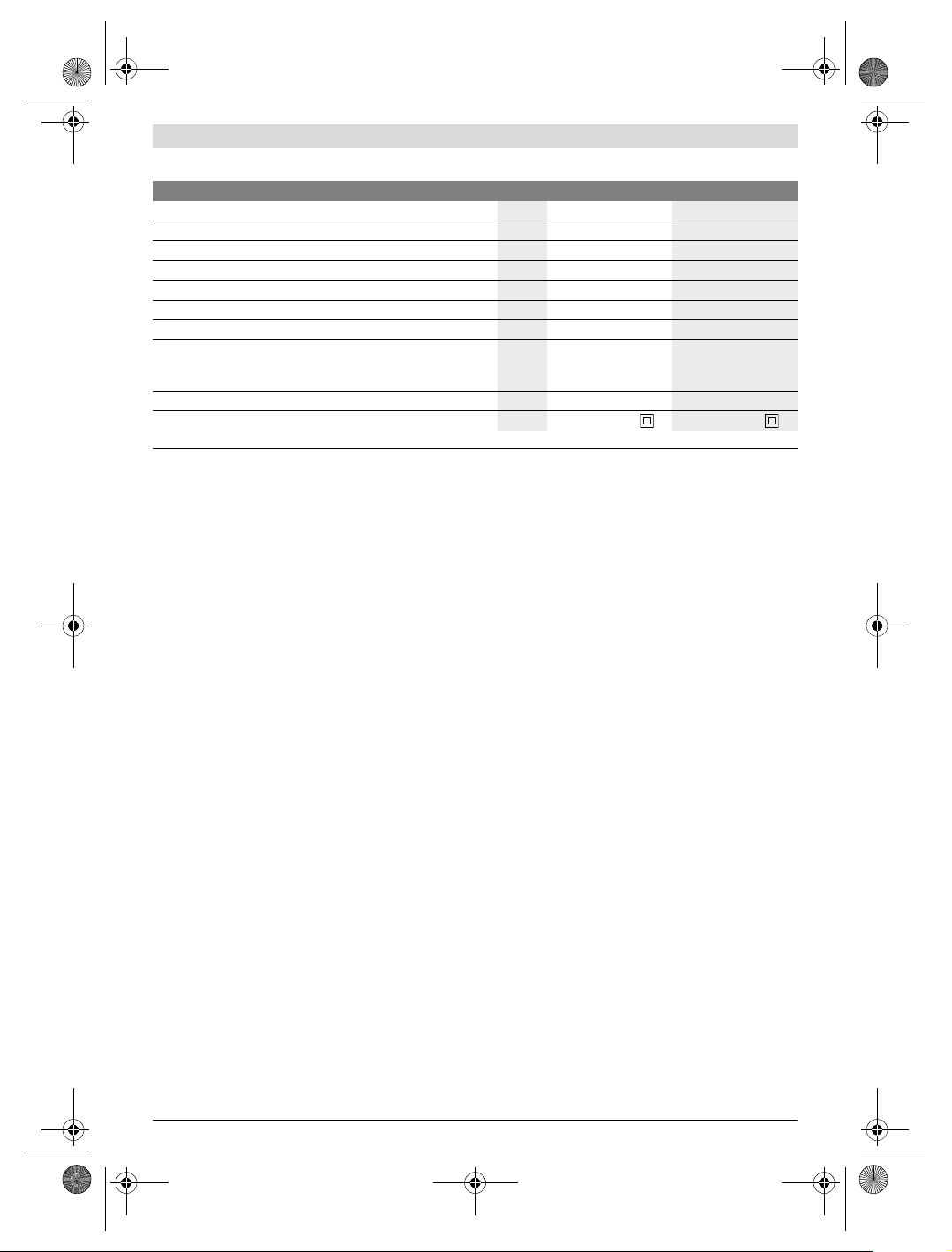
Technical Data
Assembly
Before any work on the machine itself, pull the mains
plug.
Dust Extraction
Dust from materials such as lead-containing coatings,
some wood types, minerals and metal can be harmful to
one’s health. Touching or breathing-in the dust can cause
allergic reactions and/or lead to respiratory infections of
the user or bystanders.
Certain dust, such as oak or beech dust, is considered car-
cinogenic, especially in connection with wood-treatment
additives (chromate, wood preservative). Materials con-
taining asbestos may only be worked by specialists.
– Provide for good ventilation of the working place.
– It is recommended to wear a P2 filter-class respirator.
Observe the relevant regulations in your country for the
materials to be worked.
Mounting/Replacing the Diamond Cutting Disc
(see figure A)
When mounting and replacing diamond cutting discs, it
is recommended to wear protective gloves.
Diamond cutting discs become very hot during opera-
tion; do not touch them until they have cooled down.
Always use a correctly sized diamond cutting disc with
the fitting mounting hole that corresponds with the
information listed in the technical data.
Use only diamond-tipped cutting discs. Segmented
diamond wheels may only have negative cutting angles
and slots between the segments to a maximum of
10 mm.
Mounting the Diamond Cutting Disc
Clean the diamond cutting disc 15 and all clamping parts to
be mounted.
Mount the mounting flange 14 onto the drive spindle 13.
Place the diamond cutting disc 15 onto the mounting flange
14. The direction arrow on the diamond cutting disc 15 and
the direction-of-rotation arrow on the blade guard 6 must
correspond.
Mount the clamping flange 16 and screw in the clamping bolt
18.
Hold the clamping flange 16 with the ring spanner 17 and
tighten the clamping bolt 18 with the hex key 19.
Removal of the Diamond Cutting Disc
Hold the clamping flange 16 with the ring spanner 17 and
loosen the clamping bolt 18 with the hex key 19.
Remove the clamping flange 16 and diamond cutting disc 15
from the drive spindle 13.
Operation
Operating Modes
Before any work on the machine itself, pull the mains
plug.
Adjusting the Cutting Angle (see figure B)
Loosen wing bolt 9. Tilt the machine sidewards until the de-
sired cutting angle is set on the scale 11. Tighten wing bolt 9
again.
Note: For bevel cuts, the cutting depth is smaller than the
setting indicated on the cutting-depth scale 3.
Pre-selecting the Cutting Depth (see figure C)
The cutting depth may only be pre-selected when the
machine is switched off.
Adapt the cutting depth to the thickness of the workpiece. For
optimum results, the diamond cutting disc must protrude
approx. 2 mm out of the material.
Loosen wing bolt 4. For a smaller cutting depth, pull the
machine from the base plate 10; for a larger cutting depth,
push the machine toward the base plate 10. Adjust the
desired cutting depth at the cutting-depth scale 3. Tighten
wing bolt 4 again.
Masonry Saw GDM 13-34 GDM 13-34
Article number
3 601 36A 2.. 3 601 36A 2B0
Rated power input
W13001300
Rated speed
min
-1
12000 12000
Max. diameter for diamond cutting discs
mm 114 114
Cutting discs width, min.
mm 1.6 1.6
Cutting discs width, max.
mm 2.4 2.4
Mounting bore
mm 20 15
Cutting depth, max.
–for 0° bevel angle
–for 45° bevel angle
mm
mm
34
22
34
22
Weight according to EPTA-Procedure 01:2014 kg 2.8 2.8
Protection class
/II /II
The values given are valid for a nominal voltage [U] of 230 V. For different voltages and models for specific countries, these values can vary.
OBJ_BUCH-936-006.book Page 8 Tuesday, September 26, 2017 12:39 PM