SI-F130 Manual(EN)_jpg_ Rev1.pdf - 第106页
Adjustment of H Axis Upper End OT Sensor (H-CCW) HLF-10404-01 Adjustment of H Axis Upper End OT Sensor (H-CCW) SHEET 2/3 3 Loosen the cap screws (2-M3) on sensor bracket for the H axis upper end OT sensor to move the bra…
Adjustment of H Axis Upper End OT Sensor (H-CCW)
HLF-10404-01
Adjustment of H Axis Upper End OT
Sensor (H-CCW)
SHEET
1/3
Adjustment of H Axis Upper End OT Sensor (H-CCW)
[Necessary jigs]
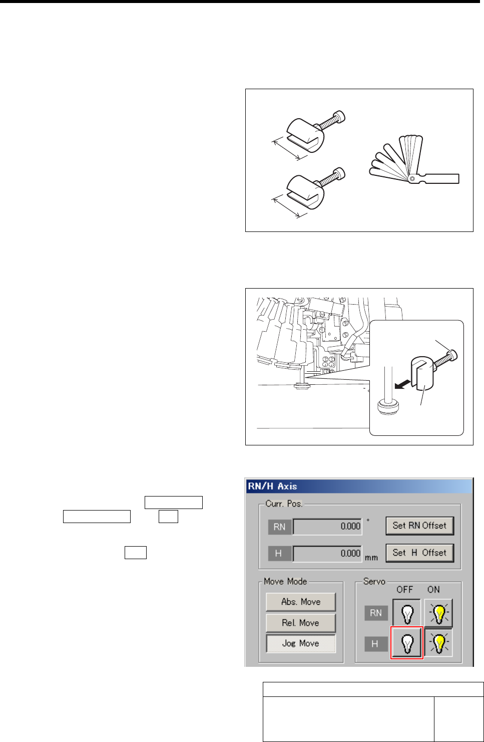
• H axis sensor adjusting jig
(L=15.5 mm, 15.0 mm)
• Thickness gauge (t=1.6 mm)
[Procedure]
1 Install the H axis sensor adjusting jig to the
inner shafts of turrets No.2 and No.12.
1. Push down the inner shaft of the tur-
ret No.2 and pinch the H axis sensor
adjusting jig (L=15.5 mm) between the
turret and inner shaft.
2. Push down the inner shaft of the tur-
ret No.12 and pinch the H axis sensor
adjusting jig (L=15.5 mm) between the
turret and inner shaft.
3. Remove the cap screw for H axis sen-
sor adjusting jig.
2 Turn off the servo for H axis.
1. Click in an order of M/C SETUP menu
ÎORG OFFSET tabÎR.H button.
RN/H Axis screen is displayed.
2. Click the servo OFF button for H axis.
Servo for H axis is turned off.
H axis sensor adjusting jig
15.5 mm
15 mm
H axis sensor
adjusting jig
Cap screw
Thickness gauge
Adjustment of H Axis Upper End OT Sensor (H-CCW)
HLF-10404-01
Adjustment of H Axis Upper End OT
Sensor (H-CCW)
SHEET
2/3
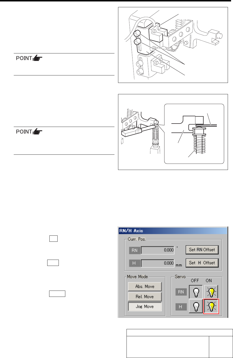
3 Loosen the cap screws (2-M3) on sensor
bracket for the H axis upper end OT sensor
to move the bracket downward (to lower
end).
The H axis upper end OT sensor is obstructed by the
dog, and the LED lights off.
Keep the cap screws (2-M3) in temporarily
tightened state.
4 Push down the H axis pusher by hand, place
a thickness gauge of 1.6 mm on the inner
shaft (No.1), and pinch with the H axis
pusher.
When pinching the thickness gauge,
slightly bring up the inner shaft from the
lower.
5 Move the sensor bracket for the H axis up-
per end OT sensor upward little by little,
tighten the cap screws (2-M3) at a position
of boundary where the lighting LED extin-
guishes, and secure the sensor bracket.
6 Remove the thickness gauge.
When the thickness gauge is removed, the LED for the H axis upper end OT sensor lights up.
7 Remove the H axis sensor adjusting jig installed on the turrets No.2 and No.12.
8 Perform origin position return of the H axis.
1. Click the ON button for the H axis
servo on the RN/H Axis screen.
The H axis servo is turned on.
2. Press the ORG button on the operation
panel with the RN/H Axis screen being
displayed.
The H axis returns to the origin.
3. Click the Return button to close the
RN/H Axis screen.
Sensor bracket
Cap screw
H axis upper end OT sensor
Thickness gauge
H axis pusher
Inner shaft
Adjustment of H Axis Upper End OT Sensor (H-CCW)
HLF-10404-01
Adjustment of H Axis Upper End OT
Sensor (H-CCW)
SHEET
3/3
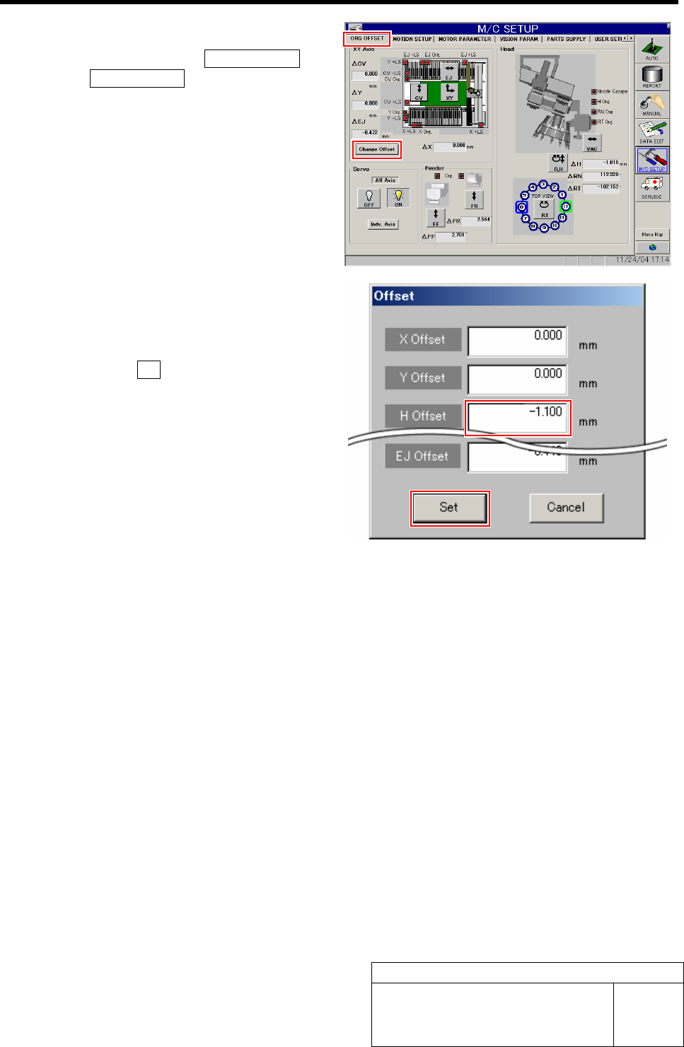
9 Input the H axis offset value.
1. Click in an order of ORG OFFSET tab
ÎChange Offset button.
Offset screen is displayed.
2. Input a value into the H Offset box so
that the gap between the upper end of
the inner shaft and the H axis pusher
should be 0.05 mm.
3. Click the Set button.
Offset value for the H axis is set.