SI-F130 Manual(EN)_jpg_ Rev1.pdf - 第109页
Adjustment of H Axis Lower End OT Sensor (H-CW) HLF-10405-01 Adjustment of H A xis Low er End OT Sensor (H-CW) SHEET 2/2 4 Loosen the cap screws (2-M3) on sensor bracket for the H axis lower end OT se nsor to move the br…
Adjustment of H Axis Lower End OT Sensor (H-CW)
HLF-10405-01
Adjustment of H Axis Lower End OT
Sensor (H-CW)
SHEET
1/2
Adjustment of H Axis Lower End OT Sensor (H-CW)
[Necessary jigs]
• H axis sensor adjusting jig
(L=15.5 mm, 15.0 mm)
[Procedure]
1 Move the inner shaft of the turret No.1 to
right below the H axis pusher.
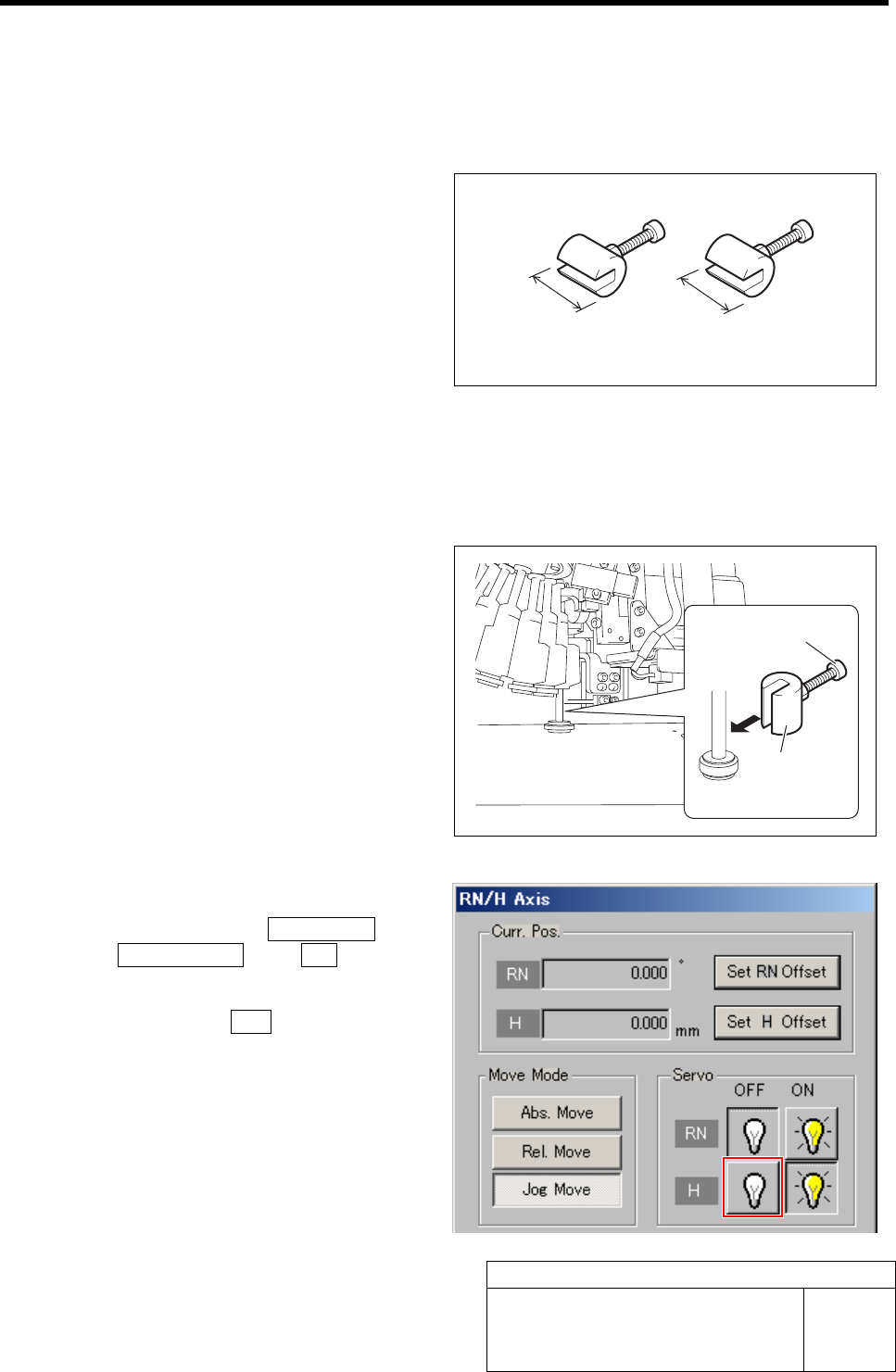
2 Install the H axis sensor adjusting jig to the
inner shafts of turret No.1.
1. Push the H axis pusher from the upper
by hand, and push down the inner
shaft.
2. Pinch the H axis sensor adjusting jig
(L=15.5 mm) between the turret and
inner shaft.
3. Remove the cap screw for H axis sen-
sor adjusting jig.
3 Turn off the H axis servo.
1. Click in an order of M/C SETUP menu
ÎORG OFFSET tabÎ R.H button.
RN/H Axis screen is displayed.
2. Click the servo OFF button for H axis.
Servo for H axis is turned off.
H axis sensor adjusting jig
15.5 mm 15 mm
H axis sensor
adjusting jig
Cap screw
Adjustment of H Axis Lower End OT Sensor (H-CW)
HLF-10405-01
Adjustment of H Axis Lower End OT
Sensor (H-CW)
SHEET
2/2
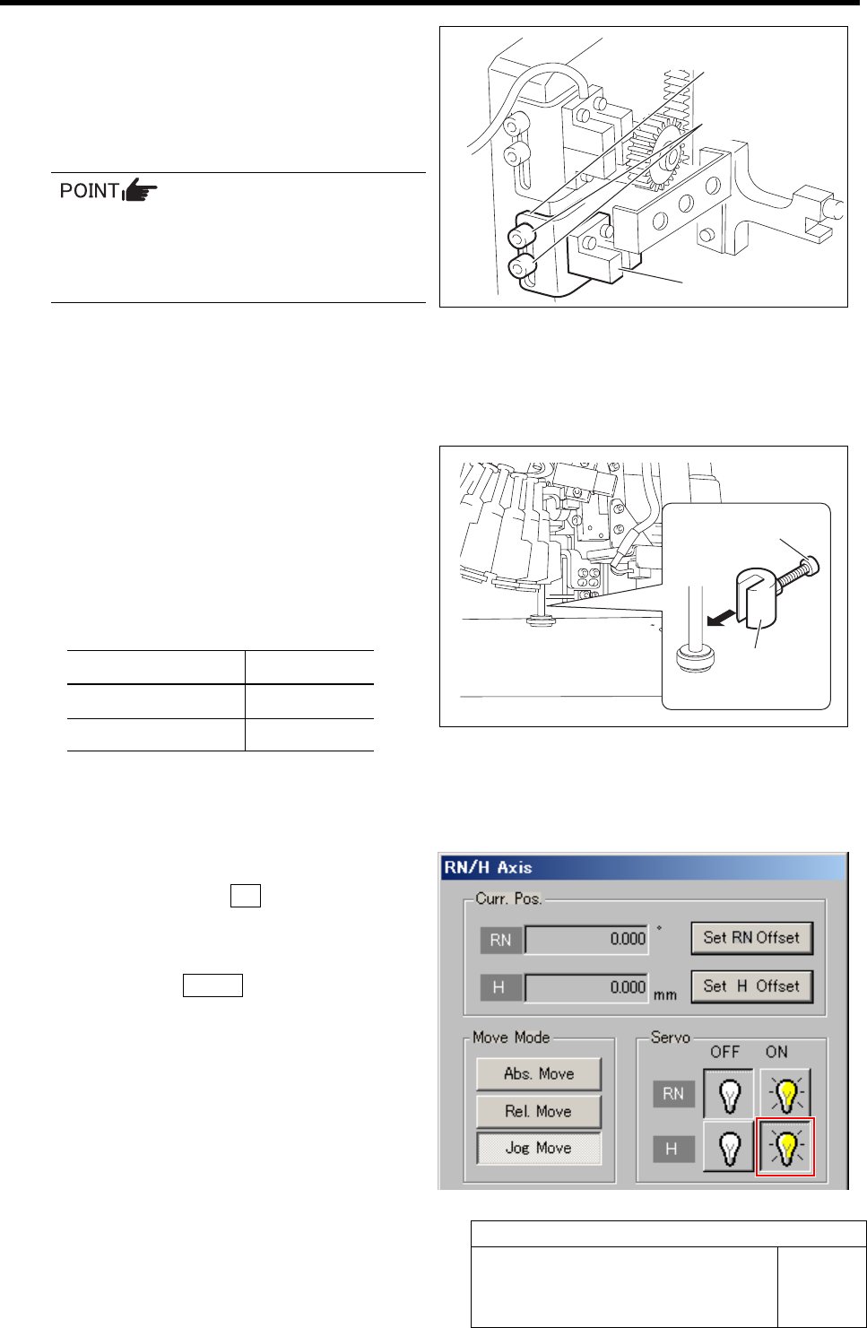
4 Loosen the cap screws (2-M3) on sensor
bracket for the H axis lower end OT sensor
to move the bracket downward (to lower
end).
The LED for H axis lower end OT sensor lights up.
• Keep the cap screws (2-M3) in temporar-
ily tightened state.
• When the H axis lower end OT sensor is
obstructed, the LED lights up.
5 Move the sensor bracket for the H axis lower end OT sensor upward little by little, tighten the cap
screws (2-M3) at a position of boundary where the lighting LED extinguishes, and secure the sensor
bracket.
6 Change the H axis sensor adjusting jig in-
stalled on the inner shaft of the turret No.1 to
a jig of 15.0 mm.
7 Check that the lighting LED for the H axis
lower end OT sensor extinguishes at this time.
Sensor setting: Dark ON
Jig used State of LED
Jig 1 (L = 15.5 mm) Lights-up
Jig 2 (L = 15.0 mm) Extinguish
8 When raising and lowering the dog for the H axis sensor, check that the H axis upper end OT sensor
does not interfere with the ORG sensor cable.
9 Return the H axis servo back to on.
1. Click the servo ON button for H axis
on the RN/H Axis screen.
Servo for H axis is turned on.
2. Click the Return button to close the
RN/H Axis screen.
Sensor bracket
Cap screw
H axis lower end OT sensor
H axis sensor
adjusting jig
Cap screw
FF/FR Axis Z-Phase Matching
HLF-10406-01
FF/FR Axis Z-Phase Matching
SHEET
1/3
FF/FR Axis Z-Phase Matching
[Necessary jigs]
• Do not use jig.
[Procedure]
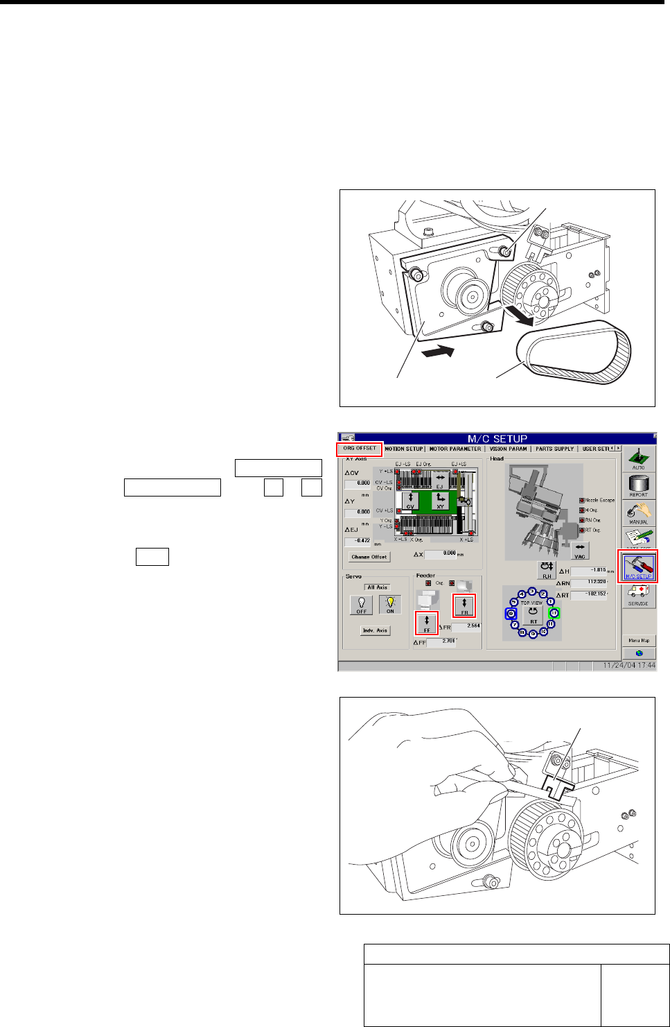
1 Loosen the cap screws (3-M4) on the F axis
motor mounting bracket.
2 Slide the bracket to the driven gear side to
remove the belt.
Temporarily fasten the cap screws for the
bracket.
3 Return the F axis to origin.
1. Click in an order of M/C SETUP
menuÎORG OFFSET tabÎFF / FR
button.
FF Axis or FR Axis screen is displayed.
2. Press the ORG button on the operation
panel with the FF Axis or FR Axis
screen being displayed
FF axis or FR axis returns to origin.
4 When the motor pulley starts to idle to return
to origin, obstruct the origin sensor with pa-
per.
The motor pulley slowly stoops with Z-phase after a
few seconds.
Cap screw
Bracket
Belt
Origin sensor