SI-F130 Manual(EN)_jpg_ Rev1.pdf - 第113页
Adjustment of FF/FR Axis Belt T ension HLF-10407-01 Adjustment of FF/FR Ax is Belt T ension SHEET 1/3 Adjustment of FF/FR Axis Belt T ension [Necessary jigs] • T e nsion block jig • T e nsion meter [Procedure] 1 Draw num…
FF/FR Axis Z-Phase Matching
HLF-10406-01
FF/FR Axis Z-Phase Matching
SHEET
3/3
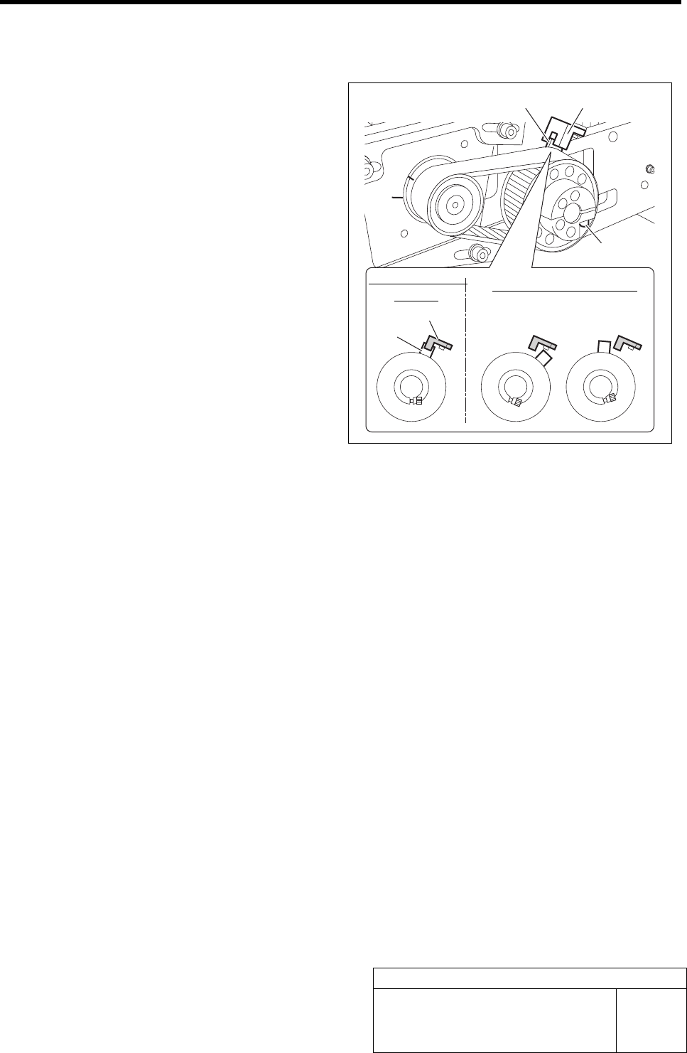
10 After adjusting the marking off line positions, fasten the split fastening screw of the driven pulley
temporarily to such an extent as to prevent the idling of the pulley.
11 Check that the dog position of the driven
pulley is coincided with sensing position of
the origin sensor.
12 Additionally tighten the split fastening screw
of the driven pulley with the dog coincided
with the sensing position.
13 If the dog is out of the sensing position, or if
the dog is found coincided nearly with the
sensing position, adjust the dog position in
the following procedure.
1. Loosen the split fastening screw of the
driven pulley.
2. After confirming the Z-phase marking
off line position, retighten the split
fastening screw.
3. Match the dog position to the origin
sensor.
Dog
Origin sensor
Origin sensor
Dog
Sensing enabled
position
Sensing disabled position
Split fastening screw
Adjustment of FF/FR Axis Belt Tension
HLF-10407-01
Adjustment of FF/FR Axis Belt
Tension
SHEET
1/3
Adjustment of FF/FR Axis Belt Tension
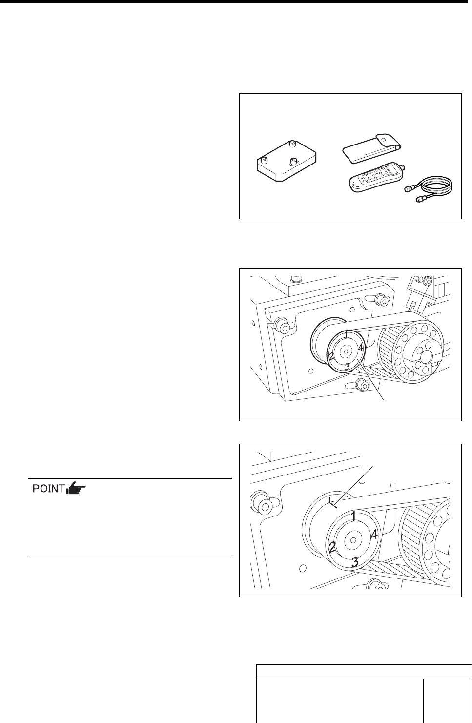
[Necessary jigs]
• Tension block jig
• Tension meter
[Procedure]
1 Draw numbers 1 to 4 in interval of 90 degree
on the motor pulley as shown in the right
figure.
2 Draw marking off line on the motor pulley
and the belt.
When re-measuring the belt tension, start
measuring No.1 at this reference line
matching position and measure in an order
of No.2, 3 and 4. (for repeatability of
measurement)
3 Set the tension meter.
WEIGHT =1.7 gf/m
WIDTH =15 mm
SPAN =57 mm
Tension block jig Tension meter
Motor pulley
Split fastening screw
Adjustment of FF/FR Axis Belt Tension
HLF-10407-01
Adjustment of FF/FR Axis Belt
Tension
SHEET
2/3
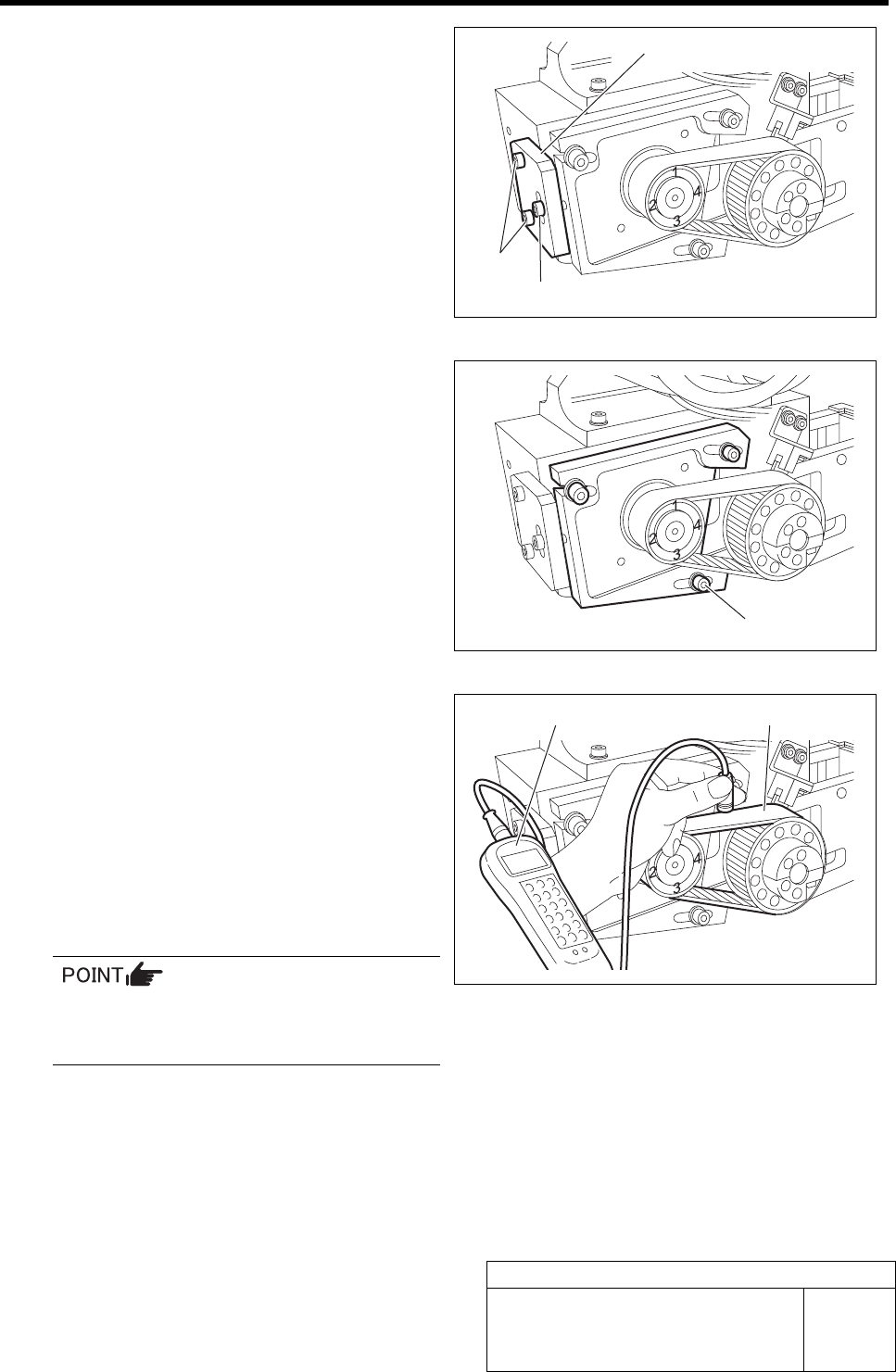
4 Install the tension block jig to the feed body.
5 Loosen the cap screws (3-M4) on the F axis
motor mounting bracket.
6 Measure the tension at positions of No.1 to
No.4 on the motor pulley in this order, and
check the position of maximum tension.
1. Set the measuring terminal of tension
meter near the belt on the middle be-
tween both pulleys.
2. When the belt is pulled by finger, ten-
sion value of the belt is displayed on
the tension meter.
For detailed operating method of the ten-
sion meter, refer to the manual attached to
the tension meter.
3. Measure the tension at positions of
No.1 to No.4 on the motor pulley re-
spectively, and check the position of
maximum tension.
Cap screw
Tension block jig
M4, W4
2-M3
Tension meter
Belt